


The Coil in a "Magnifier" Vs. Conventional configuration:
Some History:
I started this coil built as a conventional configuration and after some learning and playing around I got it to work reasonably well. I didn't play with coupling and such due to time constraints but my biggest goof was that I didn't play with the spark gap setting (distance) until much later. The spark gap distance controls the max voltage that the capacitor will charge to and consequently the largest potential spark out of the coil. I started taking pictures of the coil after I put it in the magnifier configurations so have many pictures of it that way and only lately started taking pictures of it in the conventional configuration.
The Conventional Configuration:
The first picture on the home page (Click here) is the conventional configuration and that picture is showing the performance at it's maximum output at 120VAC/15 Amp line power. Spark length is about 4.5 feet (137 cm). At this level amy 15 amp circuit breaker in my control box trips after about 30 seconds or so. I can reduce the output a bit and it can run for longer. I use this setup for most demos as it is stable and repeatable.
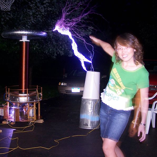
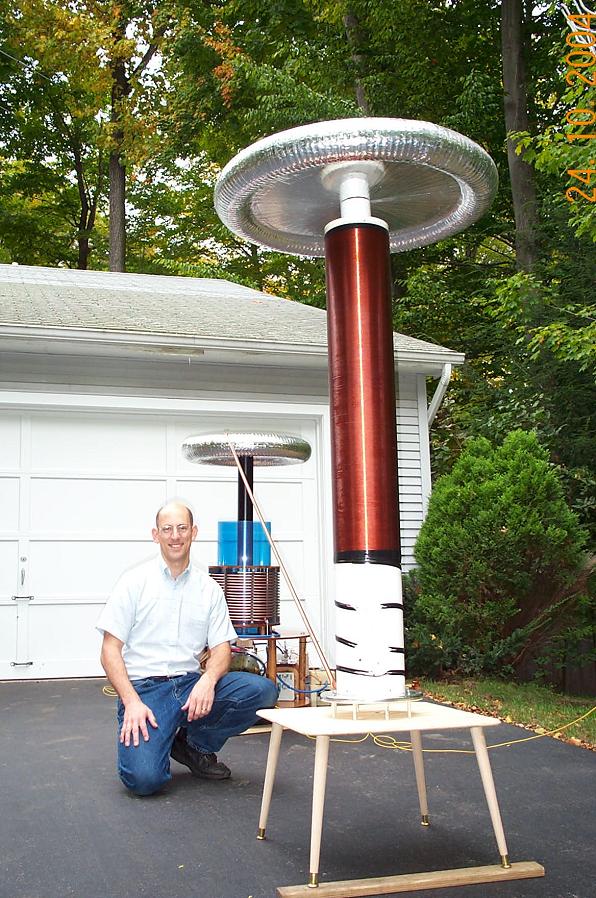
The Magnifier Configuration:
The magnifier driver section is shown below. The resonator is shown farther below. This configuration was awesome. It was producing arcs in excesss of 5 feet and was really impressive. There was two big problems that made this configuration not stable, primary to secondary insulation and the high magnetic RF field getting into the rotary motor. See below.
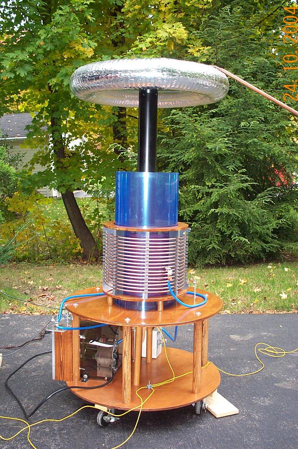
Insulation Problem:
The blue insulation you see in the photo above is 20 mil (I think) sheet lexan which I understand is not the greatest insulator but I had it and used it wrapped over a few times and slid in between the primary and secondary. I actually used it for quite a while this way and it was great but then I had to open up the spark gap and increase the voltage. I got primary to secondary arc over and got racing arcs through the lexan. Once it broke down it was cool to watch it catch fire.
Rotary Motor Problem:
I had experimented after my arc-over problem and put in more insulation and just had to crank it up to get that extra arc distance. When I cranked the power up, I put so much power into it (still 120VAC/15Amps) that I induced so much RF energy into the winding of the rotary motor that the stator winding of the motor opened up. I tried to repair it but the break was not visible.
My suggestion, keep the rotary motor or any transformer, away from the primary coil. In my conventional coil I added a line filter right at the rotary with a transorb to limit the AC peak voltage. I don't know how a transorb does at 60KHz. Because I have to have my unit portable, I had to keep the rotary where it is and just limit the motor power to 80% of 120VAC. Haven't blown it yet.
© Copyright 2006-2017. Jamie Oliver - Contents of this page are the sole responsibility of me, Jamie Oliver, and no, I'm not the British "Jamie Oliver, The Naked Chef" but I'd enjoy meeting him some day.
|
|