
![]()
RF Electronics Projects
This is the projects page specific to RF projects.
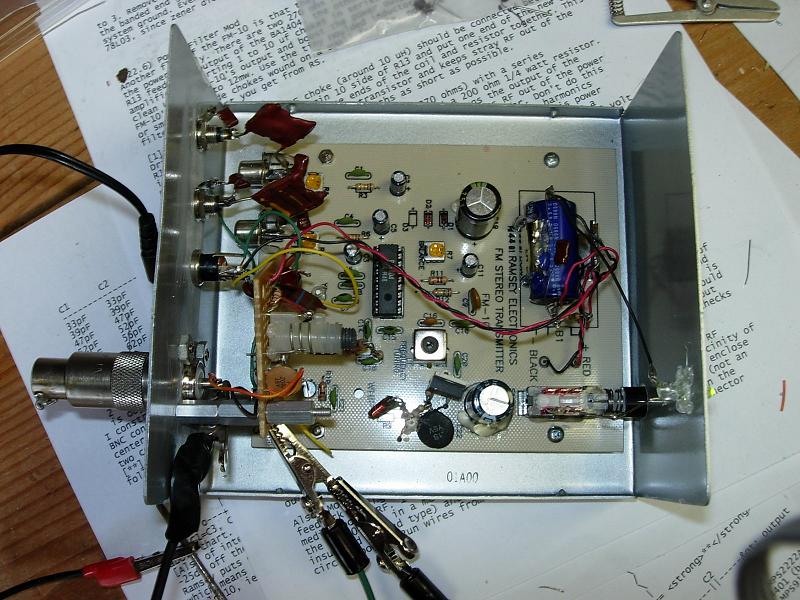
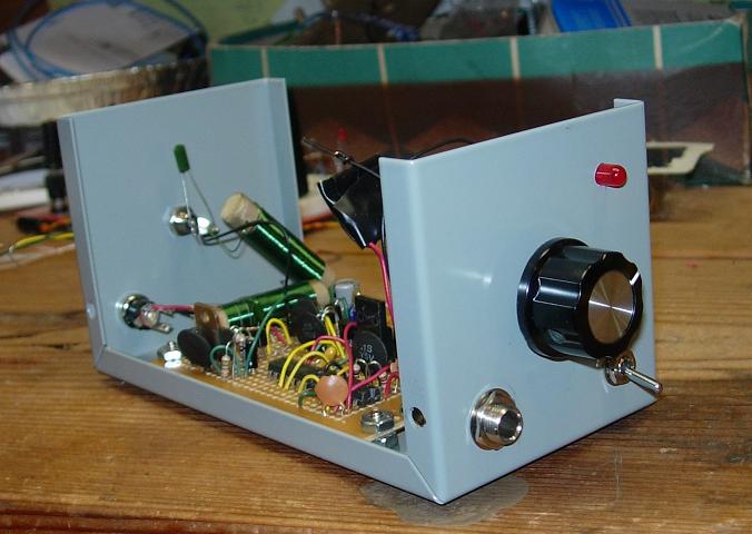
FM Stereo Transmitter
There are some photos of the Homemade FM Stereo Transmitter being built and tested. It is now plugged into it is a 300 Disc CD changer that is put in random mode to broadcast music throughout the house and property. Its range is about 1 mile. It works great as a personal radio station, that plays only the music you like without interruption. It allows going outside with a boombox or to turn on other radios tuned into it, in the house wherever you are.
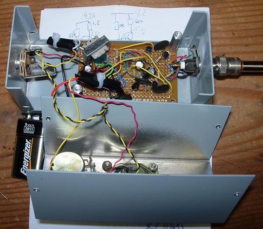
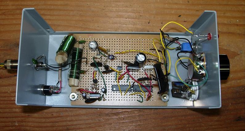
ULF-VLF receiver being built
This receiver allows the reception of lightning and other electromagnetic phenomena such as
the aurora. Allows listening to strange propagation of lightning from around the world that tunnels along the ionosphere and earth boundary.
I have listened to storms and have learned to associate the sound in the reciver to the distance of the storm. You can hear the storm approaching
on the reciver well before the appearance of the lightning over the horizon. The best time to monitor for strong lightning is when a cold front is
approaching and you are aware of its distance from radar, then it is possible to associate the sound intensity with the approximate distance of a
storm.
The earth and the ionosphere form a waveguide at very and ultra low frequencies, this allows RF energy from storms all over the globe to
reach the recivier. This is most obvious in the winter when it is obvious that there are no lightning storms in the vicinity and you can hear the
pops,clicks and whistles from distance lightning.
See the links page on this site for additional information about low frequency radio.
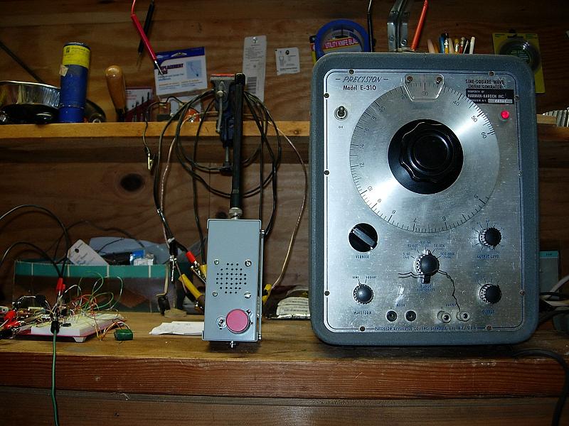
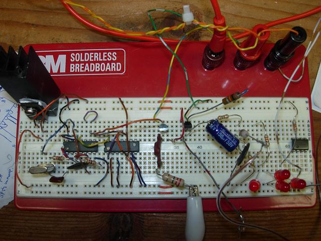
The ULF/VLF unit can also be used as
a piece of test equipment for signal tracing. It has about 1 M Ohm input impedance and very
high gain. This allows you to just wand around for signals. It is basically 4 FET stages in cascade with the final through a matching transformer
to the speaker. In the photo below the signal generator with a short stub of wire on the output
is fully audible in the receiver in the 100 - 15kHz range by putting it on the bench next to the ULF/VLF reciver.
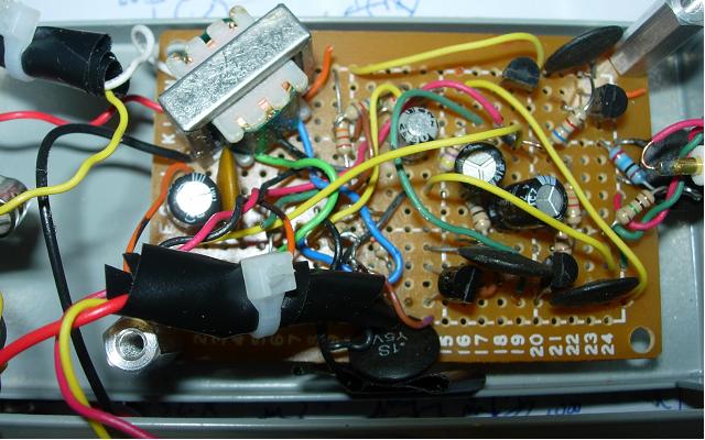
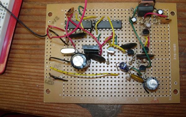
AM transmitter built and testing
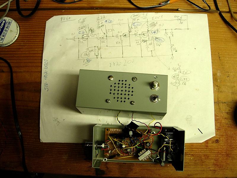
This transmitter design started out as a reverse engineering of a Ramsey AM-1 from the parts list and the schematic derived from the board layout. The AM-1 was basically breadboarded, from this it was modified to give some better quality and flexability. Higher gain transistors were chosen and a stronger output lowpass filter was designed in. Operating voltage range is 5-20VDC. Input is 1/4in jack, fed through a potentiometer to adjust the modulating level. The gain povided by the audio amplification in the circuit allows for line level input. Output from the transmitter is via a RCA phono jack, shown here with adapter feeding into a dummy load.
One of the major changes to the circuit beyond what the AM-1 provides is a crystal controlled frequency source, rather than an LC oscillator. The crystal oscillator consists of TTL parts. A 10 Mhz crystal is used with a 7400 hex inverter to create an oscillator. The output is fed into a 7490 decade divider, yielding the 1 MHz carrier frequency. Voltage is provided by a 5V 3 terminal regulator.
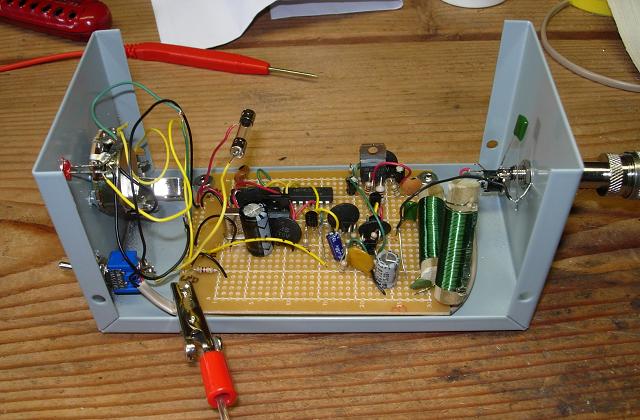
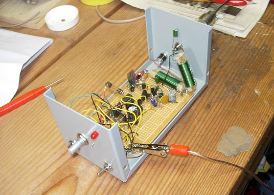
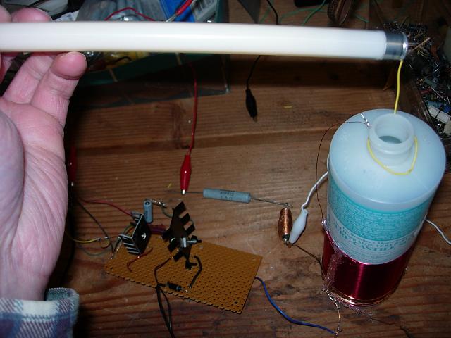
Mini Tesla Coil
This mini Tesla coil was built just to see what a Tesla coil is about first hand. It was also an exercise in building a Class D switching
type of amplifier that runs the coil. The coil itself has about 300 turns closewound 30 gauge wire and is self-resonant at 130kHz. The amplifier
consists of 2 stages of NPN power transistors. The transistors are rated for RF amplification, the driver can dissipate about 5W and the final
stage about 30W. Driving the amplifier is a signal generator set to square wave output at 130kHz. The output transistor directly feeds the primary
coil. I have tried various transistors, because they will fail easily if voltage spikes get to them. At one point I lost a few through some self
oscillation that would occur. The self oscillation would kick off occasionally and force the output transistor to run in its linear range, drawing
excessive current and overheating it quickly. A few seconds of self oscillation will blow the transistor. Bypass capacitors helped with this somewhat,
putting a resistor in line with the supply helped even more. The supply lines have chokes and it seems like the self oscillation was related to the
chokes, even a little series resistance would damp the resonance enough to kill the self oscillation.
Most important for this kind of circuit is grounding, high voltage floating or arcing back to the transistors means instant death. The signal generator
is vacuum tube so it has not been bothered by some level of high voltage at all, but I suppose if it got nailed by too much voltage it would be a
problem for it.
The sparks from the coil are not that impressive, they can reach up to an inch long. The corona discharge from the end of the coil wire does look
cool in the dark. The coil will light florescent bulbs at a distance of a few inches.
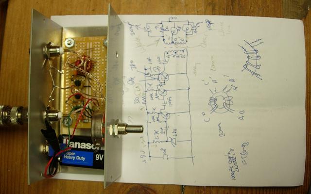
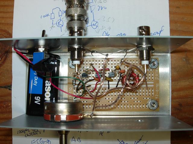
Noise Bridge
The following pictures show a noise bridge for AF/RF impeadance measurements. It uses a Zener diode and amplification to generate broadband noise.
A toroiod transformer is where the noise signal, unknown and output are balanced for a null. When the null is detected in the output
by using a reciever or meter the impedance on the R and C dials are equal to the unknown impedance.
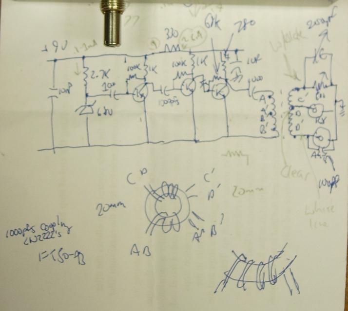
The schematic shows the details. Information on this device was obtained online by searching on noise bridge.
The site http://dj4br.home.t-link.de/index.htm has a good description. It is in German with an
English translation. It refers to a Noise Bridge as, Eine Rauschbrücke zur Impedanzmessung which translates directly to Noise Bridge for
Impedance Measuring. The design I used is influenced off of what I learned from this site In the photos below it is shown without the variable
capacitor for the RX-bridge.
![]()
Original Build Date:11-07-2007
Last updated 11-07-2007