Ford Super Duty
4x4 Ball Joint and Front Brake
Replacement
2004 F250 4x4 XLT Sport Crew Cab
Click Here for a PDF version of this article
Out of nowhere one day, I heard a nasty squeaking noise from under my truck when I turned the steering wheel. I had my Dad turn the wheel while I laid under there with a stethoscope and, unfortunately, pinpointed the problem to be the lower right side ball joint. Upon further inspection I found that the boot had been torn at some point leading to the failure. Indeed I found some play in that joint when I jacked up the truck and shook the tire. The upper joint and both left side joints still seem fine with almost 75k miles on the clock.
Once you decide that its time to replace your ball joints, the first thing you should do is get some good penetrating oil and liberally spray the ball joints. If you do this every other day until all your parts come in, it will be alot easier to get everything apart when its go-time.
I used Racerguy's ball joint replacement thread on FTE along with Guzzle's Powerstroke Tech Articles as a guide for this project. I only put this page together to add a few additional pictures of the process as Racerguy and Guzzle have the procedures covered really well.
This project turned into almost a full front end rebuild (minus steering linkage and wheel bearings). The following list is everything I did during this job:
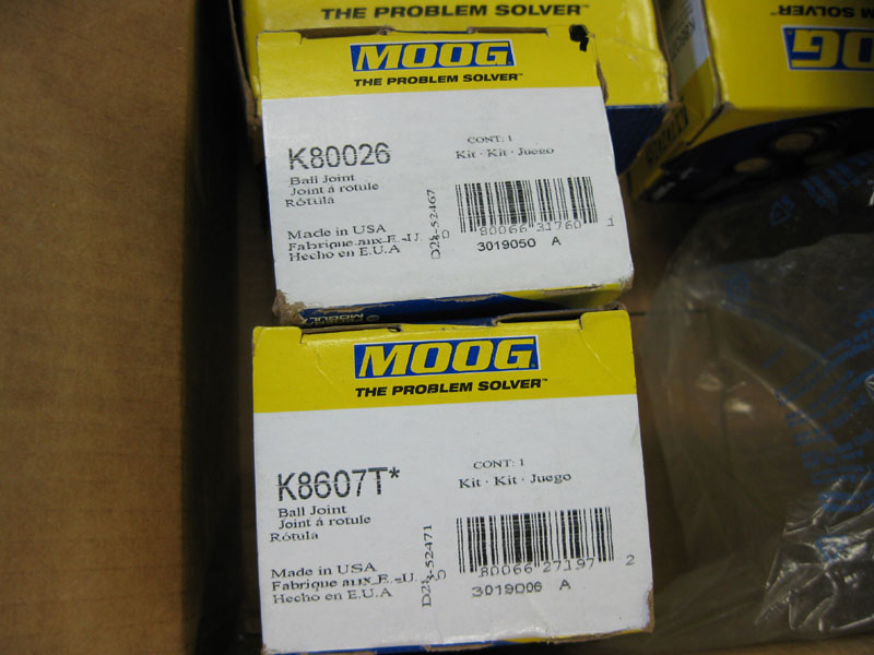
Moog Ball Joints & new axle seals
Front brakes - Powerslot cryo rotors and Hawk pads
Front axle u-joint replacement
TOOLS & PARTS I USED
- Moog # K8607T lower ball joint, quantity 2
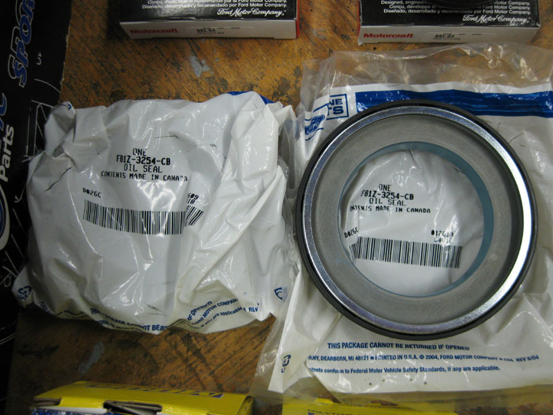
- Motorcraft # F81Z-3254-CB large axle seal, quantity 2
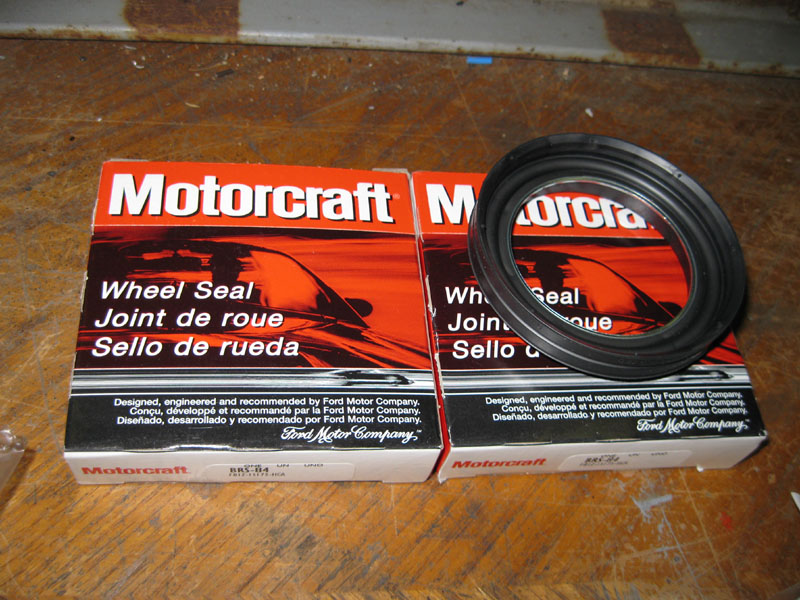
- Motorcraft # F81Z-1S175-HCA axle dust seal, quantity 2
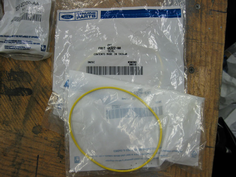
- Motorcraft # F81Z-4A322-AA yellow o-ring, quantity 2
- Motorcraft # 4C3Z-1K106-AA black o-ring & retainer clip kit, quantity 1
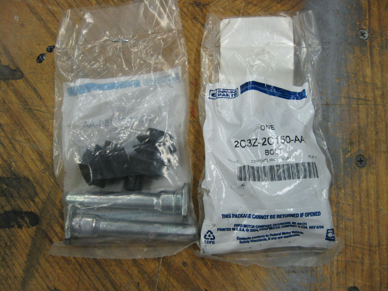
- Motorcraft # 2C3Z-2C150-AA slide pin kit, quantity 2
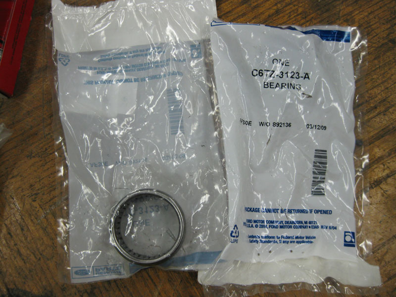
- Motorcraft # C6TZ-3123A needle bearing, quantity 2
- Powerslot Cryo #126.65086CSR, 126.65086CSL brake rotors
- Hawk LTS # HB302Y.700 brake pads, quantity 1 set
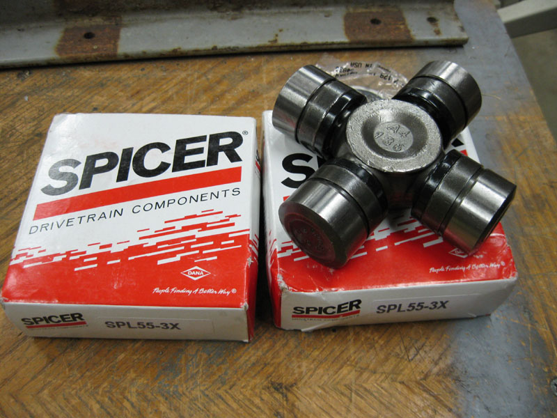
- Spicer # SPL55-3X front axle u-joint, quantity 2
- Safety glasses
- OTC # 7249 ball joint press
- OTC # 6731 Ford adapter update kit
- Pitman arm puller
- Large (6") 3-jaw puller
- Small (3") 3-jaw puller
- Homemade seal driver tool
- Large pickel fork tool
- Crow bar
- 6" C-clamp
- 1/2 drive ratchet
- 1/2 drive 3" extension bar
- 1/2 drive torque wrench
- 1/2 drive 33mm socket
- 1/2 drive 21mm socket
- 1/2 drive 13/16" socket (for ball joint press)
- 1/2 drive 1-1/8" socket
- 1/2 drive impact wrench
- 3/8 drive ratchet
- 3/8 drive 17mm socket
- 3/8 drive 3/4" socket (for tie rod puller)
- 1/4 drive ratchet
- 1/4 drive 8mm socket
- Snap ring removal tool
- Needlenose pliers
- Slip joint pliers
- Flat screwdrivers, several sizes
- Brass punch
- Various hammers (ball pein, soft faced, etc)
- 12 ton press
- Floor jack
- Jack stand
- Wheel chock
- CRC Brakleen parts cleaner
- Pennzoil #705 multi-purpose white grease
- Valvoline Durablend bearing grease
- Brake caliper grease
- Cotterpins
- Threadlocker, blue
- Grease gun
- Old scissor jack
- Scotchbrite pads
- Long cable ties
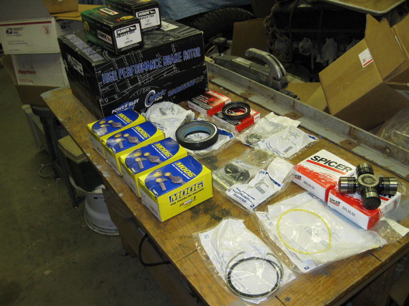
After much reading I decided to go with Moog ball joints as many others have. They are high quality replacements that are greaseable, unlike the originals. Here's a shot of all the parts I used in this process.
Now, on to the procedure. Unless otherwise noted, all of the pictures below are of the passenger side. I did the passenger side first and missed taking a few pics along the way, so I took them when I did the driver's side. Not that it matters, I just want to avoid any confusion.
Chock one of the rear tires, jack up one side, remove the tire, and place a jack stand under the axle.
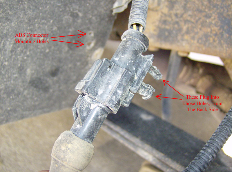
Disconnect the ABS sensor wiring. The connector is located behind the splash shield. I found it easiest to just push the connector assembly away from the splash shield and then disconnect it.
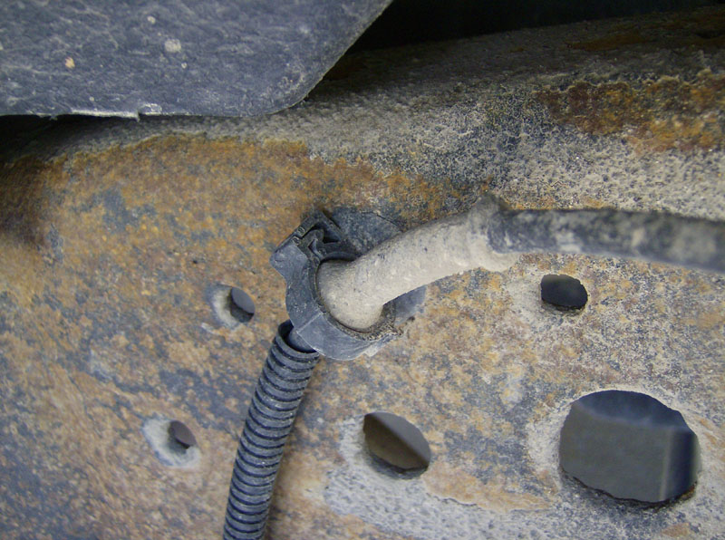
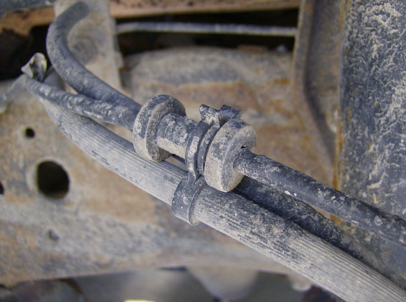
Disconnect the ABS wiring from the frame and two other places where it's attached to the brake hose.
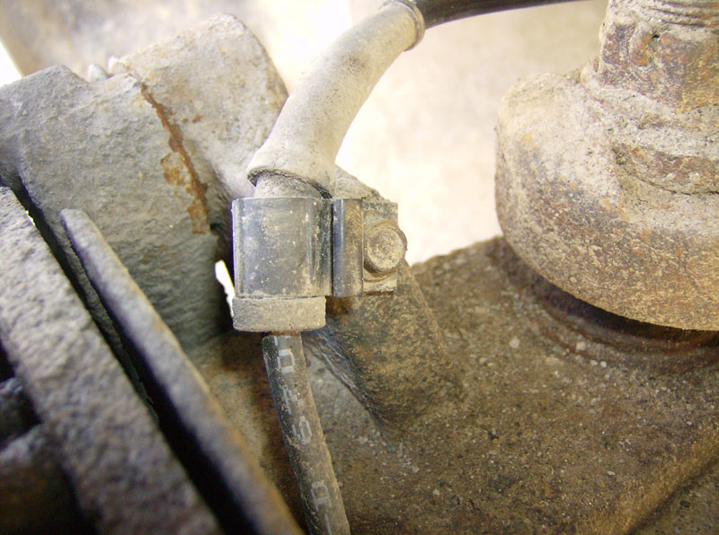
Disconnect the ABS wiring from the knuckle by removing the 8mm bolt.
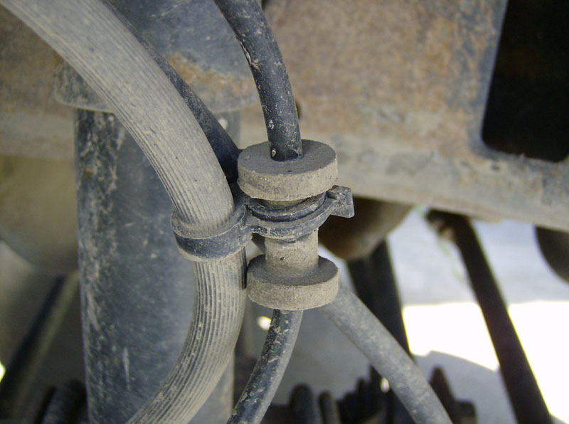
Disconnect the vacuum tube, if you have ESOF (auto locking) 4x4 hubs. I've read about folks breaking the vacuum port, if this happens, the replacement part number is F81Z-4022-BA.
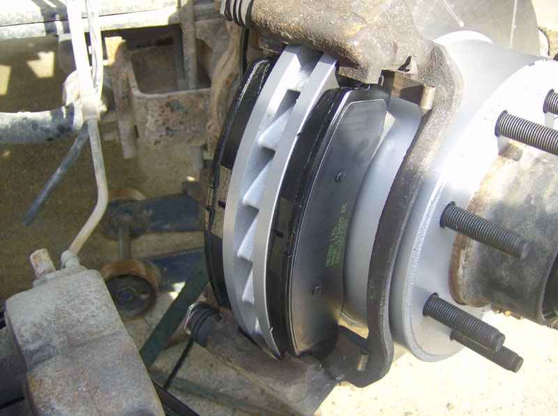
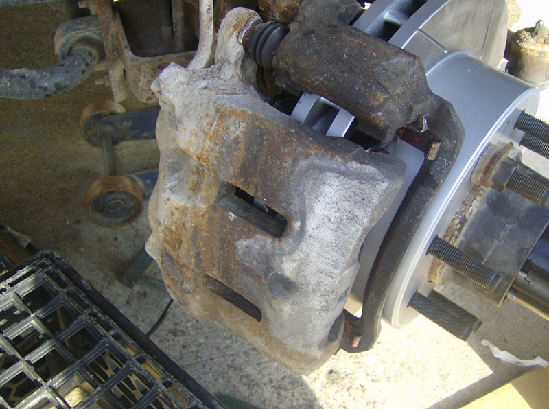
Since I was replacing my brake pads and rotors during this process, I disconnected the caliper from its mounting bracket. If you are not replacing brake pads, you can skip the next few steps and just remove the entire assembly at once. But, if you're replacing pads like I did, remove the two 17mm bolts holding the caliper to its mounting bracket.
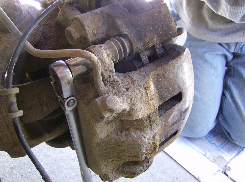
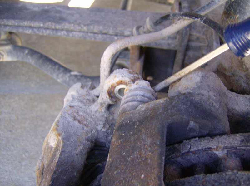
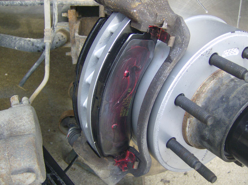
Next use a small screwdriver to pry the caliper away from its mounting bracket. If it doesn't move easily, you might need to pry around on the inner brake pad to push the caliper pistons in a little bit to give you some slack. I was able to remove it without doing this.
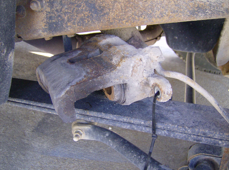
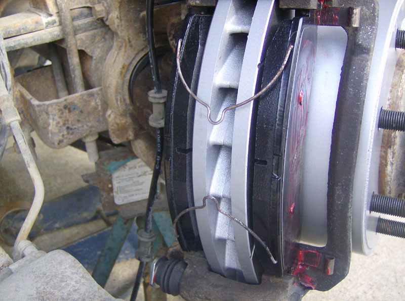
Once removed, set the caliper on the spring and secure it with a cable tie or similar.
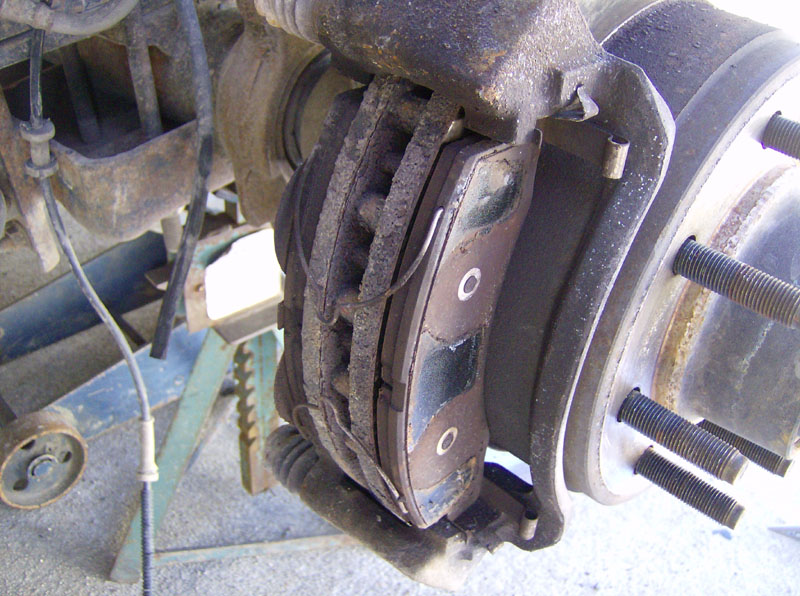
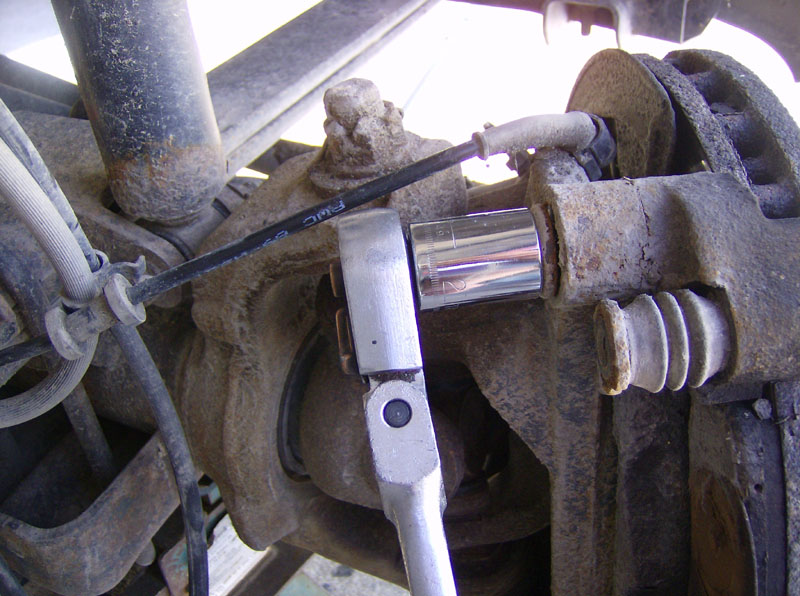
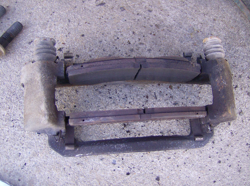
Remove the two spring clips from the brake pads. Then remove the caliper bracket and pads by removing the two 21mm bolts that hold it to the knuckle. Note that if you skipped down here from a few steps above that you will be removing the bracket, caliper, and pads all at once.
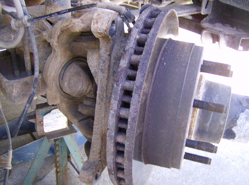
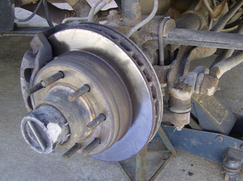
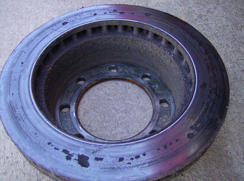
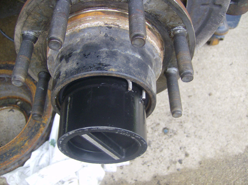
Next, remove the brake rotor. Some folks report this as being a real pain, but mine basically fell off. Looks like my brakes were in worse shape than I thought! I only felt a slight jump in the brakes after driving several (~5) miles down fairly steep mountains, but they were obviously in need of help.
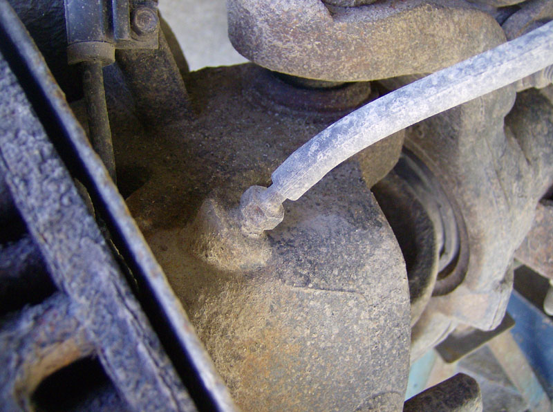
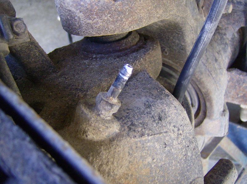
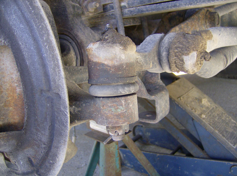
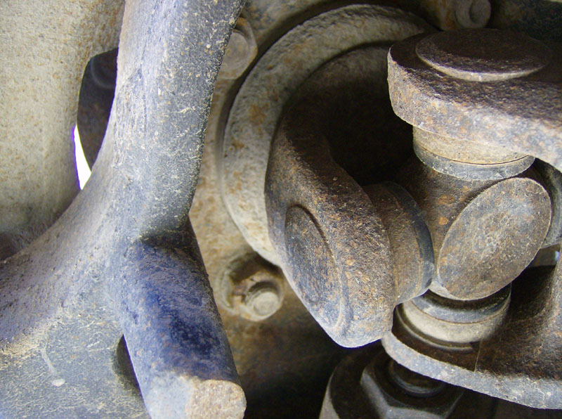
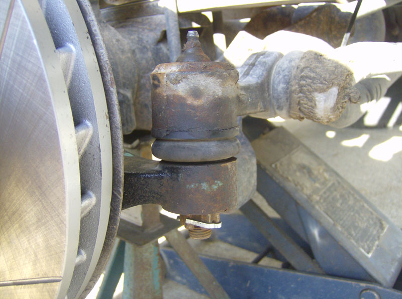
Disconnect the tie rod end from the knuckle. First remove the cotter pin, then remove the 21mm bolt. I used my harbor freight pitman arm puller to separate it. You could also use a pickel fork tool but its more likely to damage the boot than the puller.
Secure the steering linkage to the spring with a cable tie or similar.
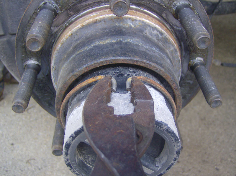
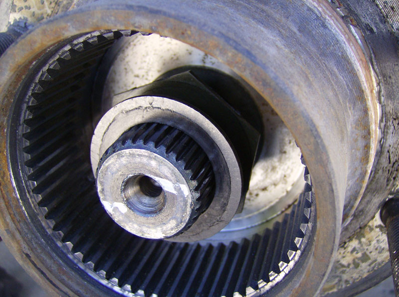
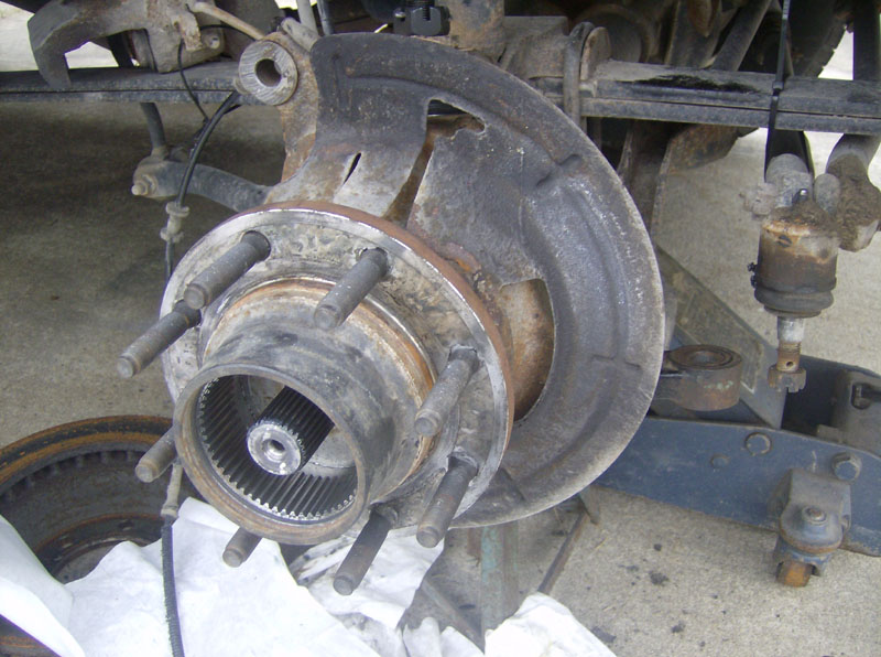
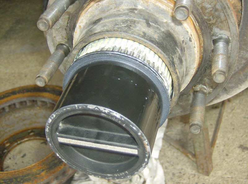
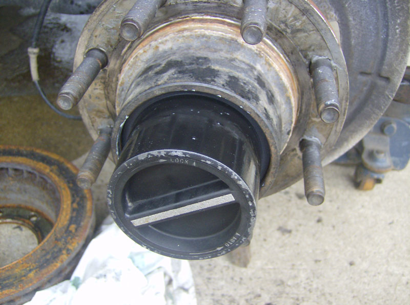
Remove the hub by first removing the big retaining ring with a pair of pliers.
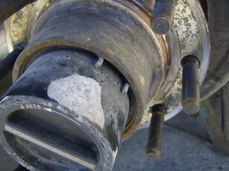
This pic was taken on the driver's side hub.
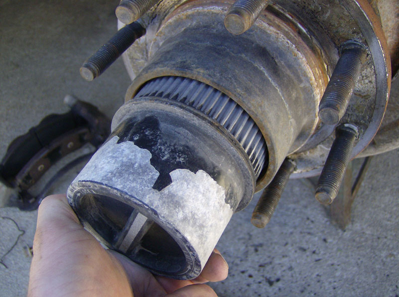
Remove the hub by pulling it straight out. Some folks also report that this step might require some persuasion, but again, mine basically pulled right out.
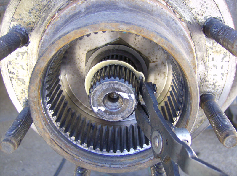
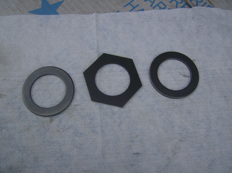
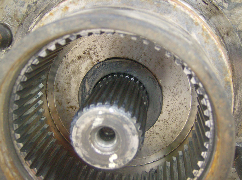
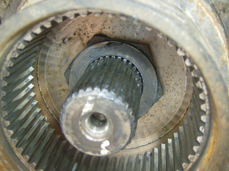
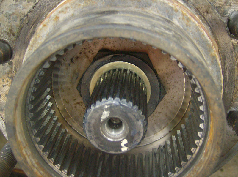
Remove the snap ring with a snap ring tool.
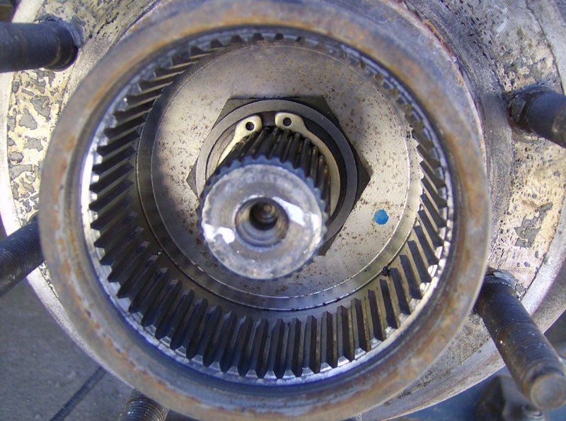
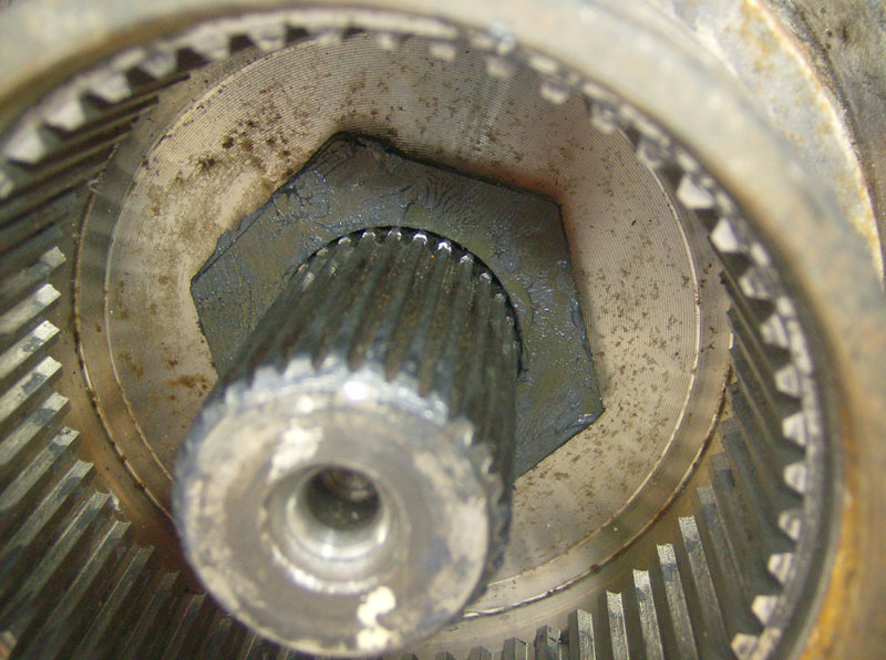
Then, remove the thrust washer, hexagon shaped washer, and the other thrust washer.
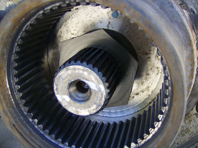
This pic was taken on the driver's side hub.
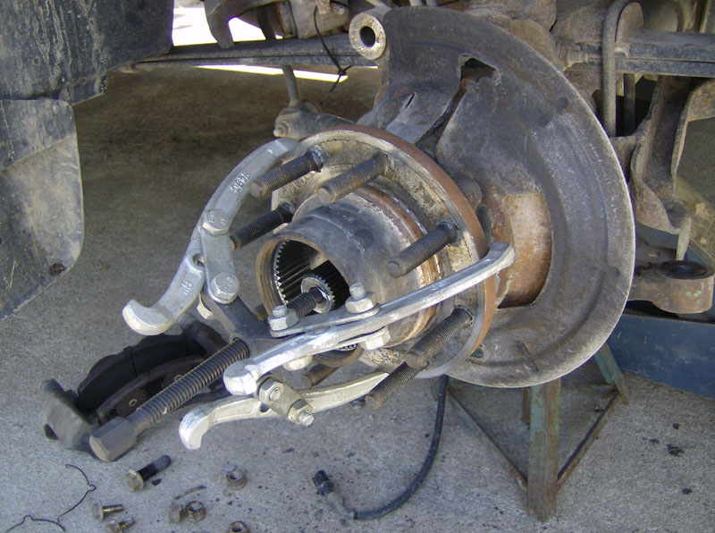
Now its time to remove the hub/wheel bearing assembly. Start by removing the four 21mm nuts on the backside of the knuckle. You can see three of them in this pic.
Once the nuts were removed, I used a large 3-jaw puller to remove the bearing assembly. Some folks drive a thin chisel or gasket scraper between the bearing and knuckle to get it loose. Others use a punch and hammer the studs out from the back. Be sure to have new studs on hand for that approach. The 3-jaw puller worked like a charm though.
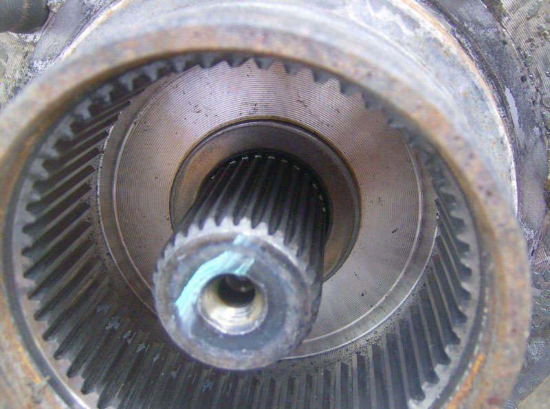
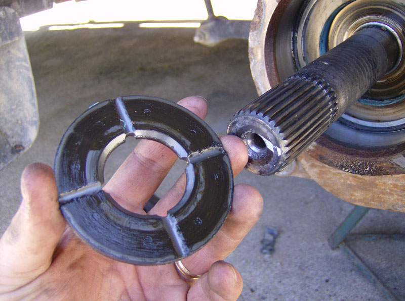
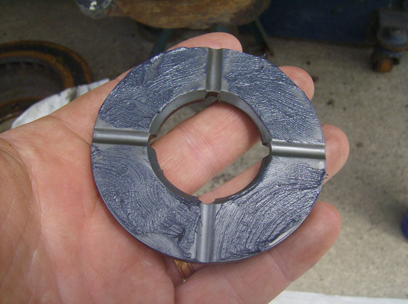
Remove this thrust washer. Note that the four grooves face inboard, this is important for reassembly.
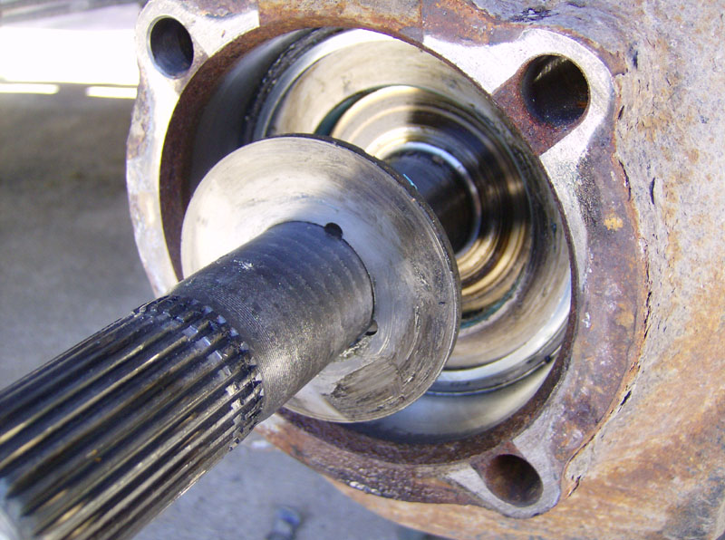
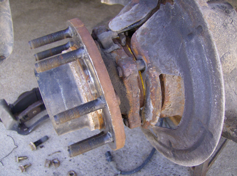
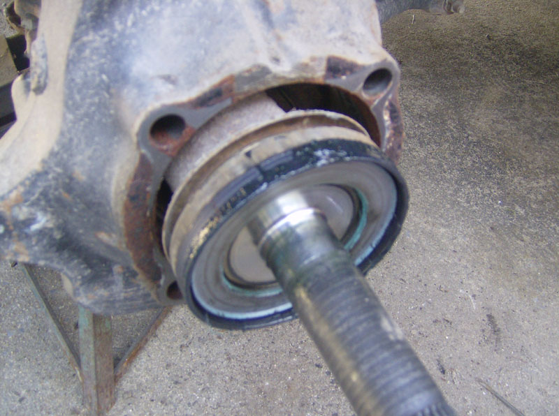
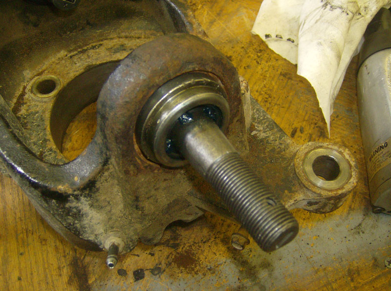
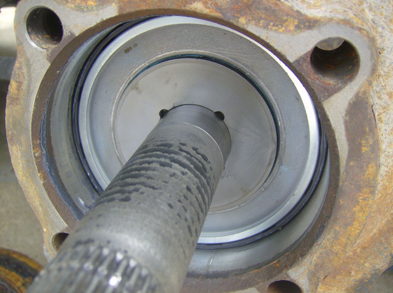
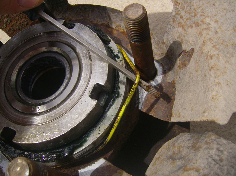
Next, remove the axle shaft. This part was fairly difficult for me. That big seal really put up a fight. After quite a bit of prying on the axle shaft (near the dust seal) I was able to get it free. Remove the big seal with a screwdriver and hammer. The first two pics below were taken of the driver's side.
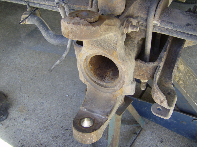
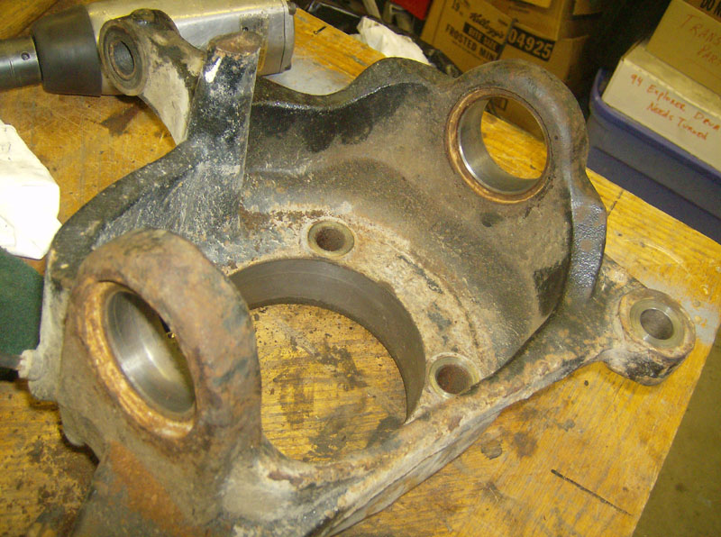
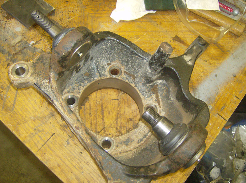
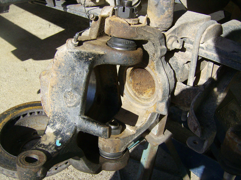
Here's the knuckle, ready to be removed.
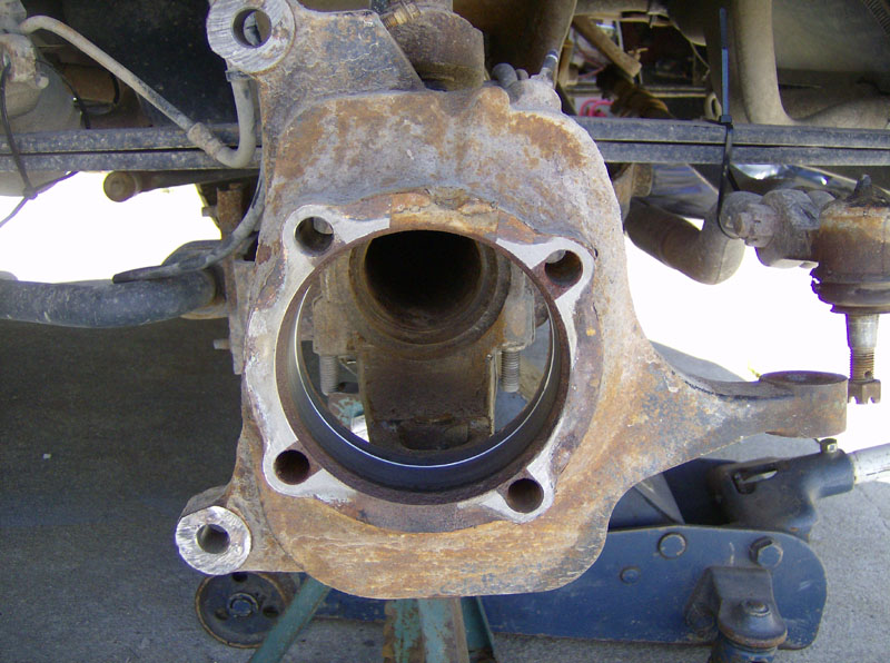
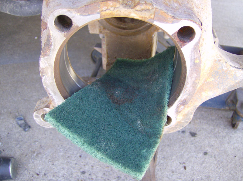
Before removing it, I cleaned up the bore with a Scotchbrite pad.
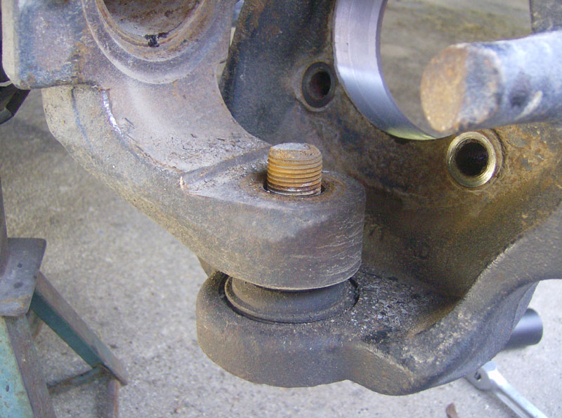
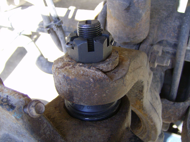
Remove the cotter pin and nut for the top ball joint. Actually, my cotter pin was rusted so bad that I ended up just shearing it off with the nut. No worries since none of these parts will be reused with the Moog ball joints. I used a 1-1/8" socket for this nut. Also, take note of the orientation of the camber sleeve. It shouldn't move but if it does, you need to put it back where it was, or go get an alignment done.
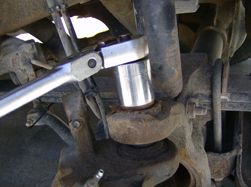
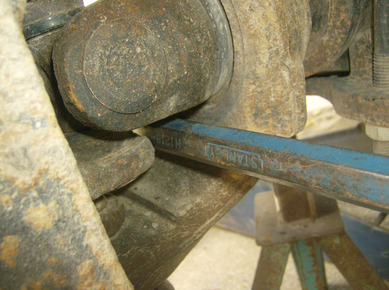
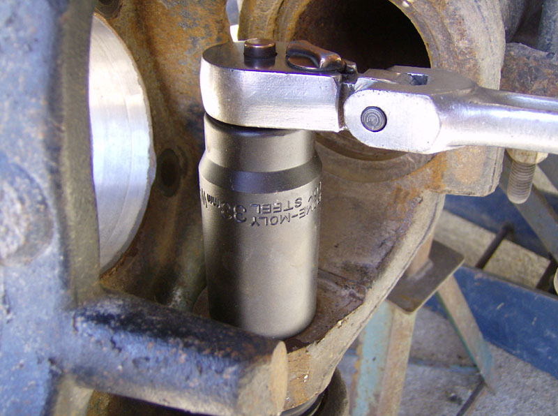
Remove the nut from the lower ball joint with a 33mm socket. The next two pictures were taken of the driver's side.
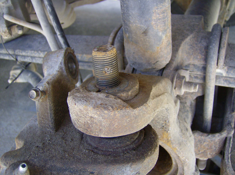
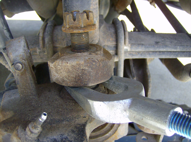
Now that both nuts are removed, run the top nut back on a few threads to catch the knuckle when it pops loose. I used a pickel fork tool to separate the upper ball joint.
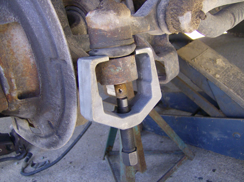
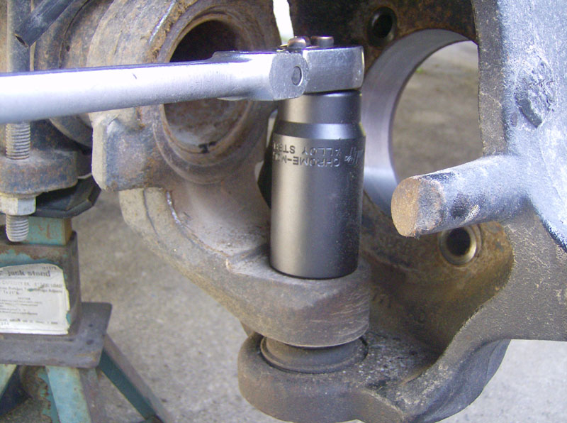
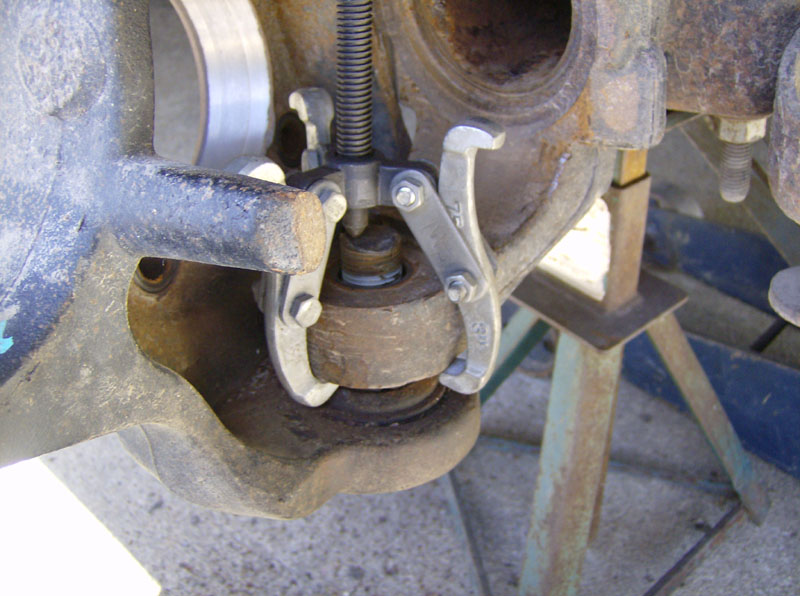
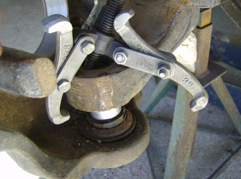
I didn't have a pickel fork tool big enough to separate the lower ball joint, so I rigged up a small 3-jaw puller to break it free.
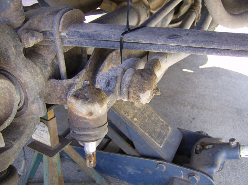
Once both ball joints are free, remove the nut from the top one, and remove the knuckle.
Now take the knuckle to a workbench to replace the ball joints. I bought the OTC ball joint tool to do this but you can rent/borrow similar tools from some auto parts stores. You can also hammer them out. I found that it is MUCH easier to use an impact wrench on the ball joint press, unless you have some good way to clamp the knuckle down. Trying to tighten the ball joint press with a ratchet results in a significant wrestling match with the knuckle, even with two people. You don't have that problem when using an impact wrench.
All of the ball joint removal and replacement pictures were taken of the driver's side knuckle.
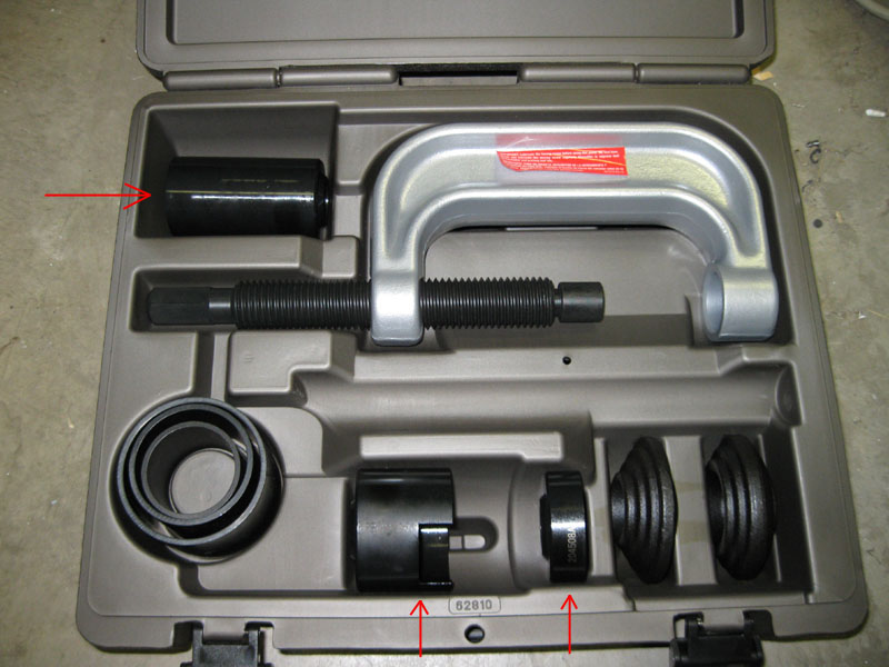
Here's the ball joint press I bought. Not the cheapest route, but I work on 4x4 trucks quite a bit so I figured it was a reasonable investment. I also purchased the Ford adapter upgrade kit, that gives you the three parts with red arrows below.
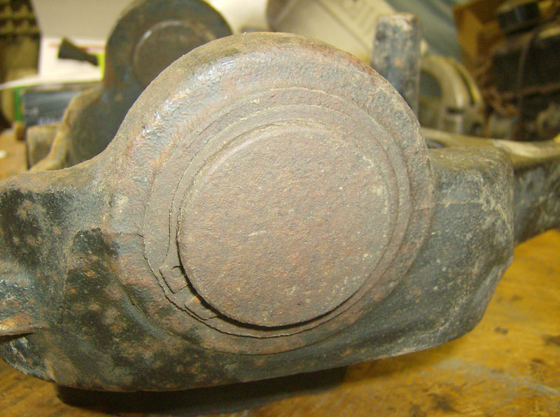
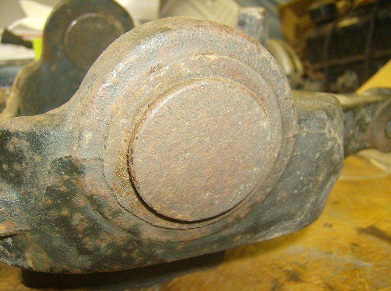
Start by removing the snap ring from the lower ball joint.
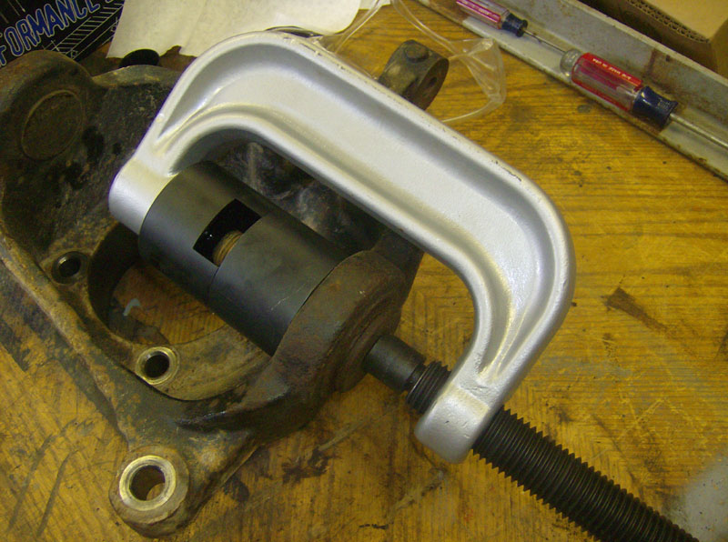
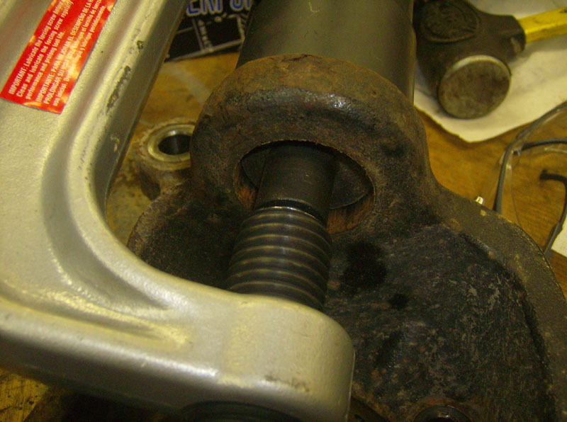
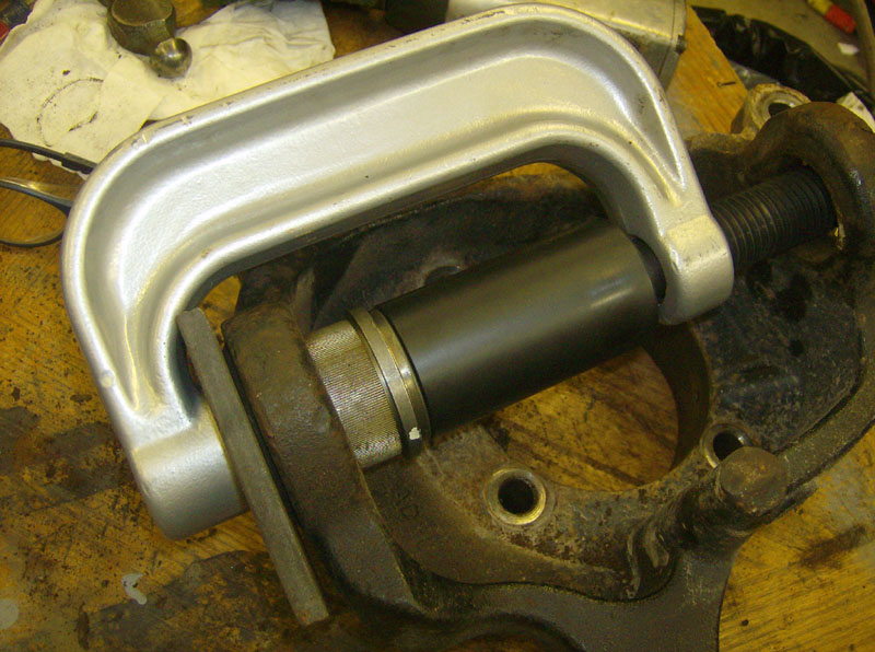
Then rig up the ball joint press as shown and use an impact wrench with a 13/16" socket to drive the old joint out.
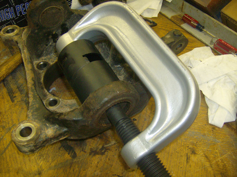
Next, rig up the press to remove the top ball joint. Its not shown, but the threaded part of the press must pass through the hole where the lower ball joint was.
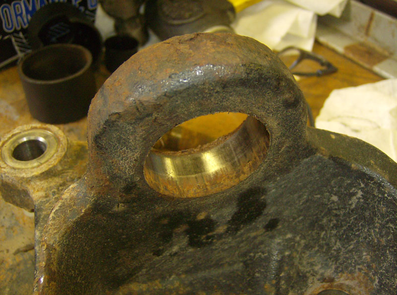
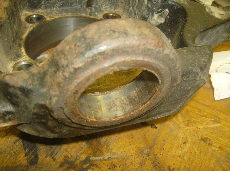
I took a minute to clean up the ball joint areas. A little Scotchbrite in the bores and a small screwdriver to clean up any debris from around the top of the holes.
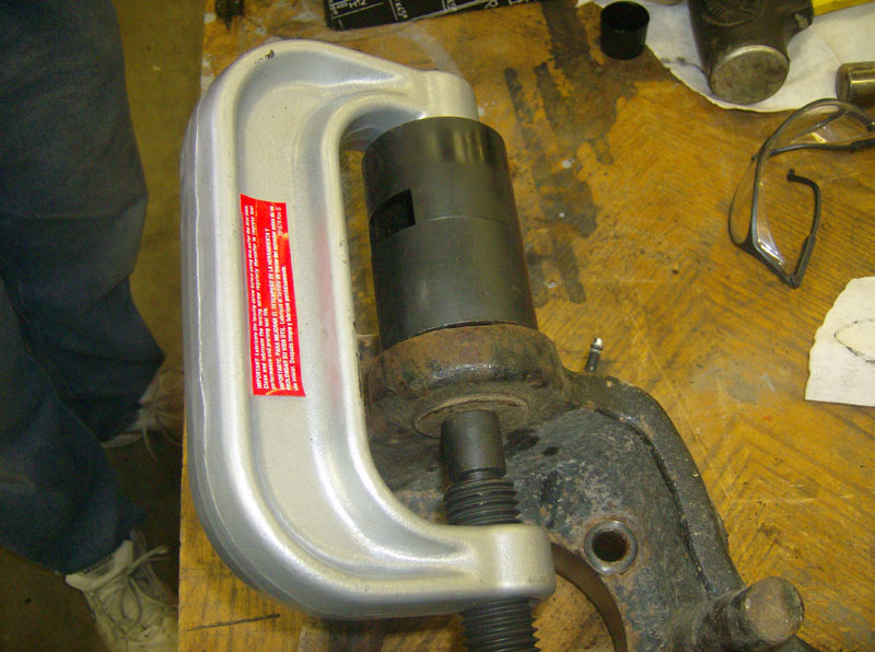
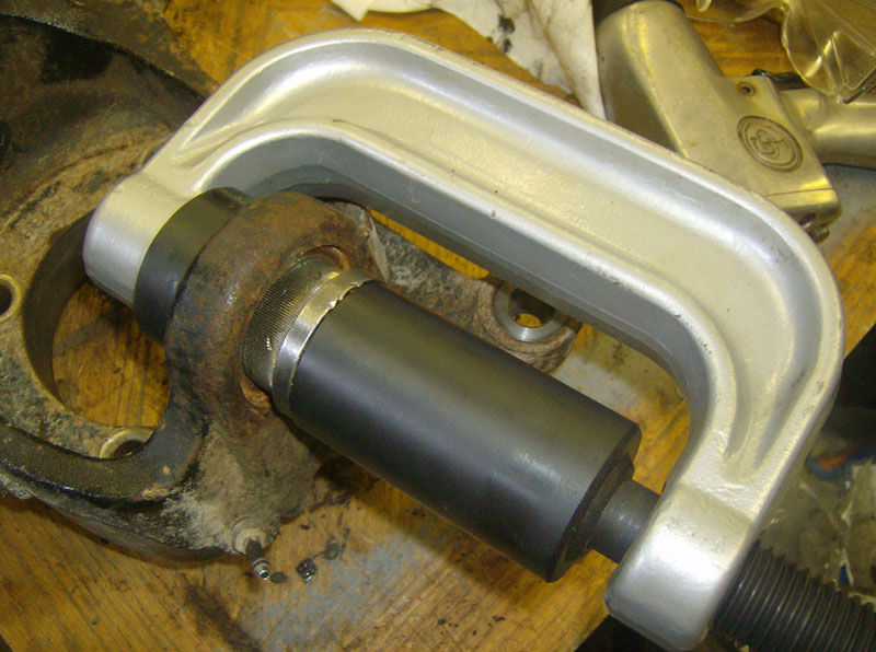
Now its time to install the new ball joints. Start with the bottom one, as the threaded portion of the press has to pass through the top joint's hole. Run the press with a ratchet to make sure the ball joint starts straight. Then drive it home with the impact wrench.
Note that I had a flat piece of steel at the bottom of the press in this picture. That's because the press didn't open quite wide enough to fit the receiving cup (shown in the 4th pic down from here) until the ball joint was partially installed.
Set up the press and install the top ball joint.
This picture shows the receiving cup at the bottom of the press, mentioned above.
Install the snap ring on the bottom ball joint, the dust boots on both of them, and you're done.
Now, the pictures shown are of the passenger side again, unless otherwise noted.
At this point I replaced the axle u-joint. To see that process click here.
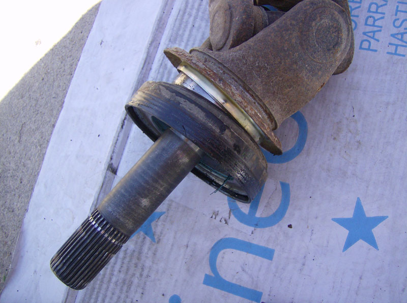
Install a new dust seal on the axle shaft.
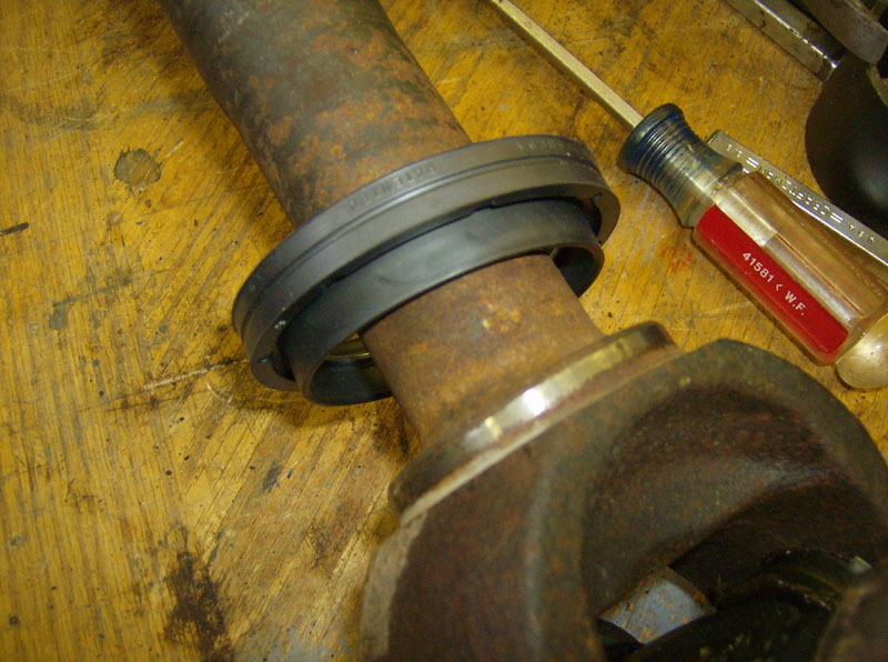
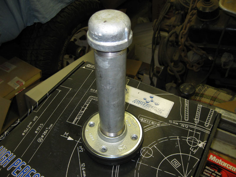
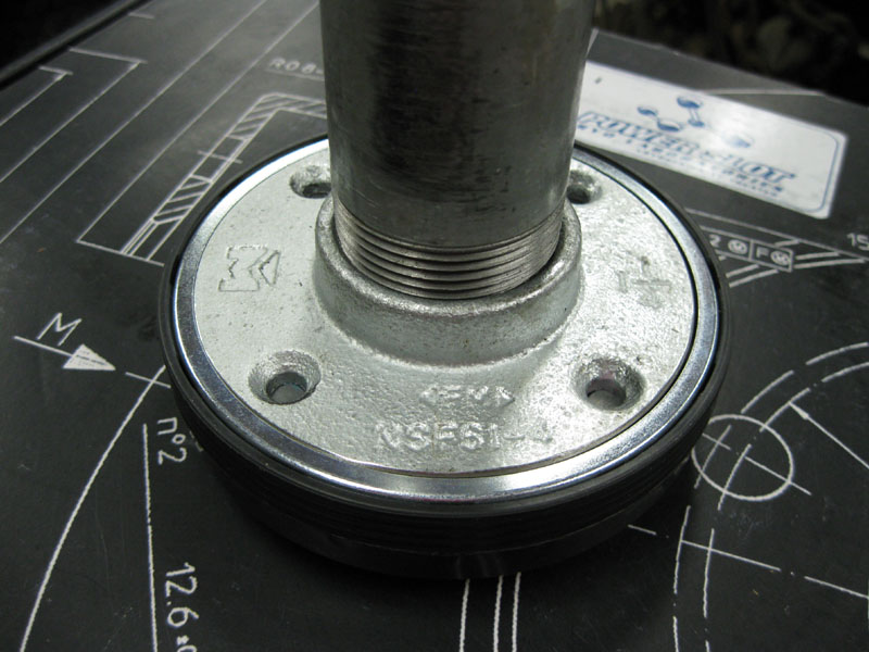
Now a little info about the seal driver tool required to install the big axle seal. Someone posted this idea in Racerguy's thread on FTE. Its made of 1-1/4" galvanized pipe parts -- an 8" pipe, a cap, and a flange. The diameter of the flange is too big so some time on the grinder will be required. I had a machinist friend of mine turn it down on a lathe to 3.875" and face it off so it would be square.
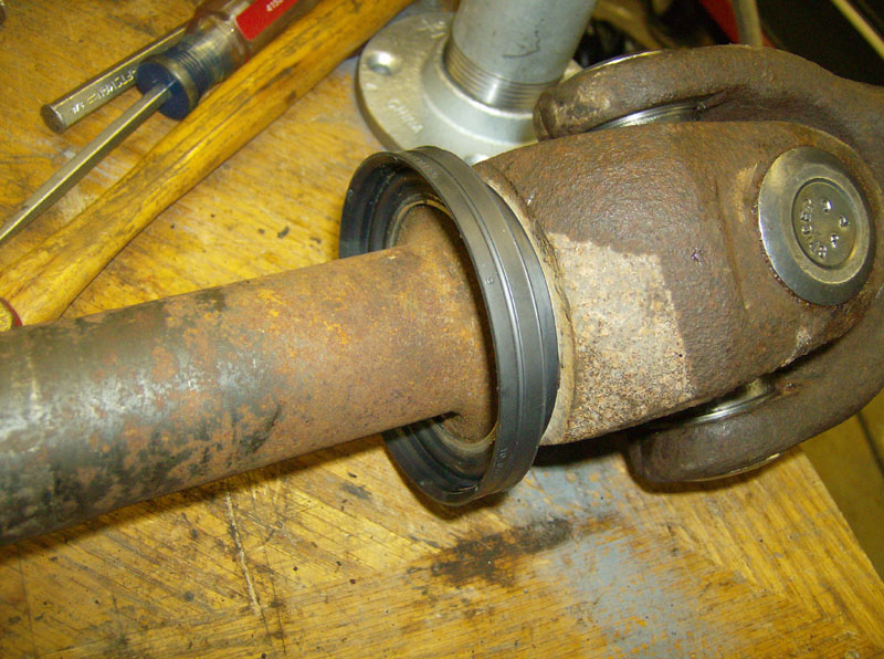
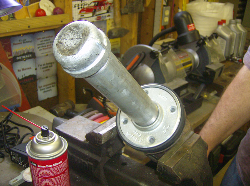
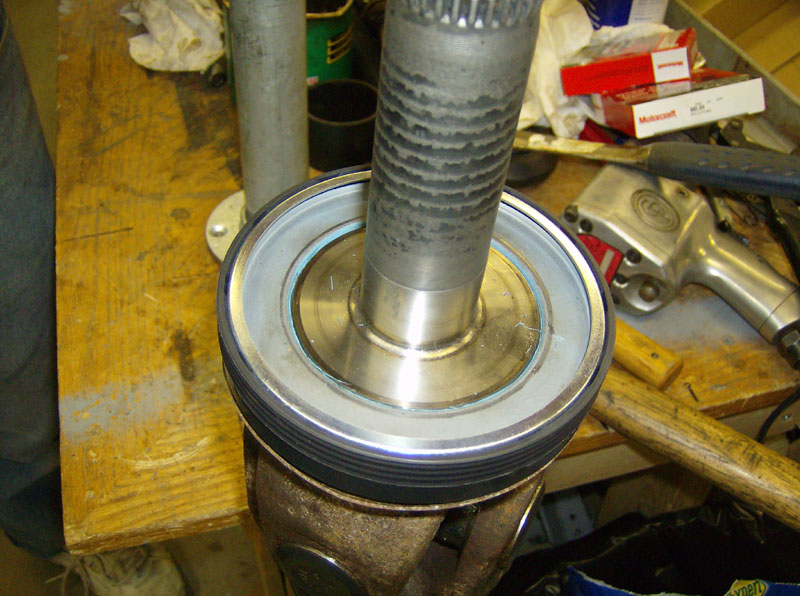
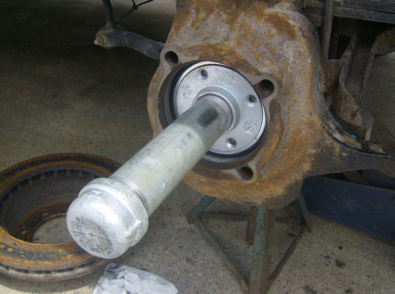
Drive the big axle seal on using the home made seal driver tool. For some reason I didn't expect it to take so much force to install the seal. Its a tight fit!
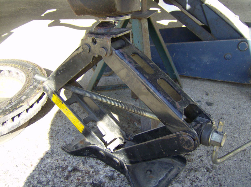
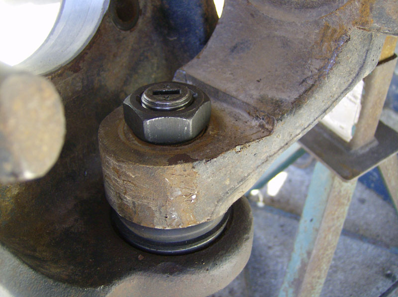
Now, reinstall the knuckle on the axle housing. Install both nuts finger tight. Then tighten the lower nut to 150 ft-lbs. Before I could get it fully tight, it began to spin. So, put an old scissor jack under it and applied only a small amount of force and I was able to torque it down. I did not have to do this on the driver's side.
Torque the upper nut to 70 ft-lbs and install the new cotter pin.
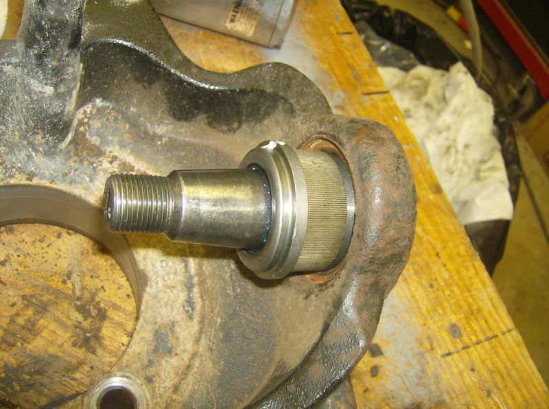
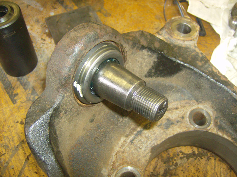
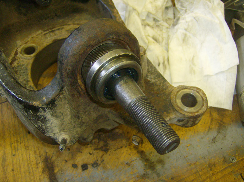
Here's the knuckle fully installed.
Apply a layer of axle grease on the rubber part of the big seal and reinstall the axle. Once you feel the axle splines line up, you can drive the axle in using the same tool you installed the seal with.
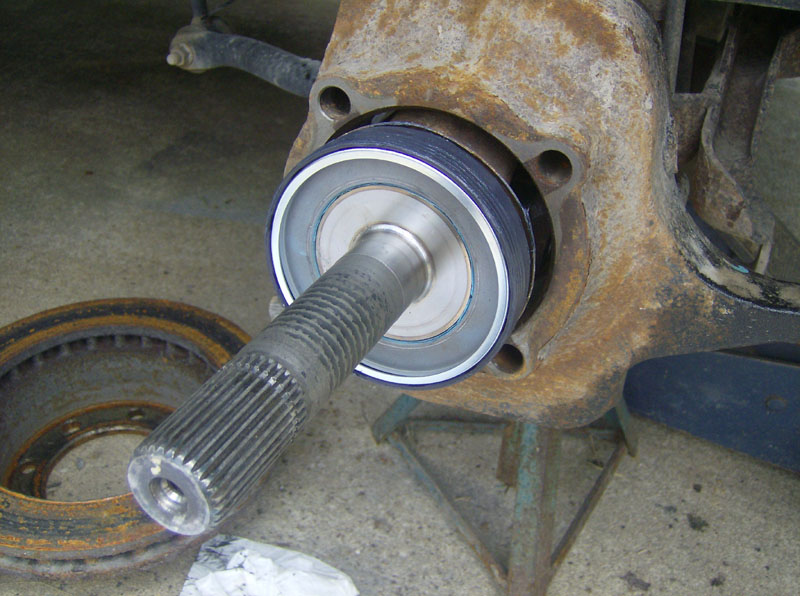
Apply a thin layer of grease to the slotted thrust washer and install it, note the grooves go inboard!
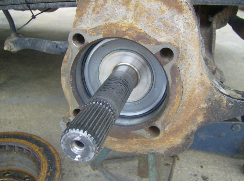
Before installing the hub/bearing assembly, be sure to grease the needle bearing or replace it. I chose to replace mine, to see that process click here.
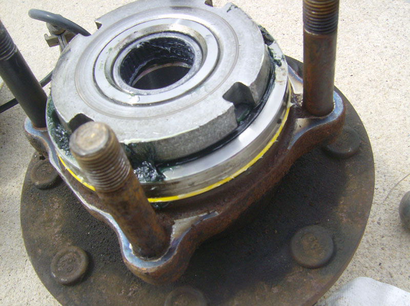
Also before reinstalling the hub/bearing assembly, be sure to replace the yellow o-ring. Remove the old one, clean up the groove, apply a little general purpose white grease to the new o-ring, and install it.
Many thanks to SpringerPop from FTE for the following section of this write-up!
Before re-installing the hub/bearing assembly, you might want to shoot some lithium based wheel bearing grease into the assembly. Even though this is a sealed bearing unit, you can accomplish this by inserting the grease through the ABS sensor hole. I did not do this during this process (because I didn't know that you could even do this!) but I will next time I'm in there. You don't have to have the hub off of the truck to do this. After much research, the recommended grease for this is Chevron Delo NLGI #2.
Here's a good thread on FTE that discusses this process -- Greasing Your Main Wheel Hub Bearings
Here's another good thread on FTE about this -- For Those Greasing Their Front Wheel Bearings
Install the hub/bearing assembly on to the knuckle and tighten the four nuts to 135 ft-lbs.
Apply a thin layer of grease to the outer thrust washers and install them in this order. Then install the snap ring.
This would be a good time to service the auto locking hubs. To see that process, click here. If you do not service the hubs, you should at least replace the black o-ring to ensure a good vacuum seal to keep the hubs working properly.
Apply a little white grease to the hub splines and to the face that the black o-ring contacts, and reinstall the hub. Once you feel the outer splines line up, you might need to reach back and turn the axle a bit to line up the inner splines. The hub should slide in with very little force.
Install the hub retaining ring.
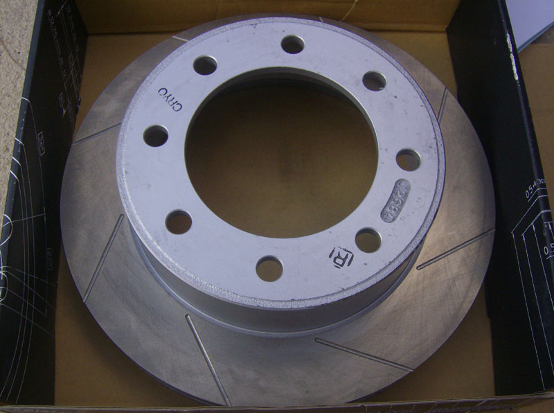
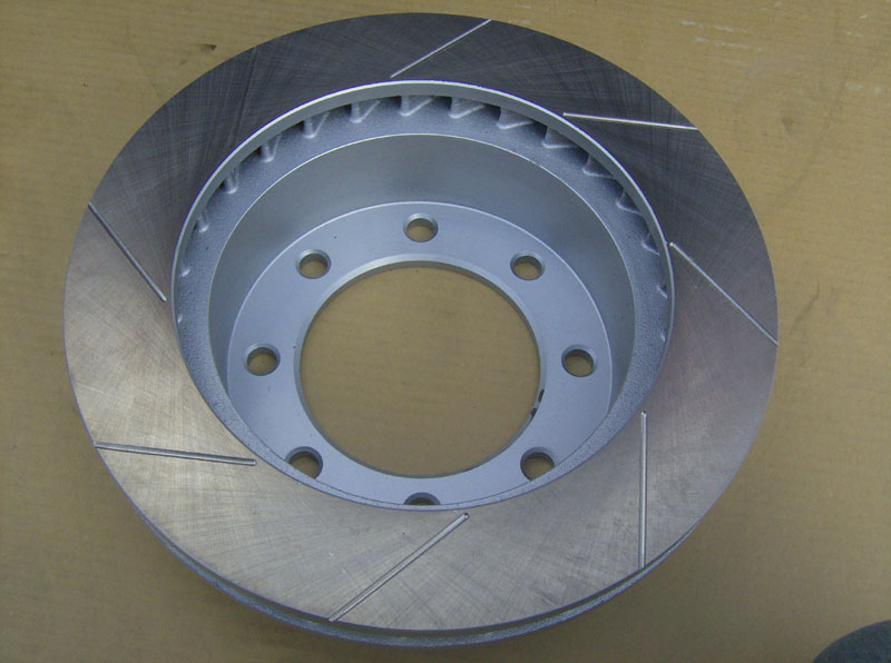
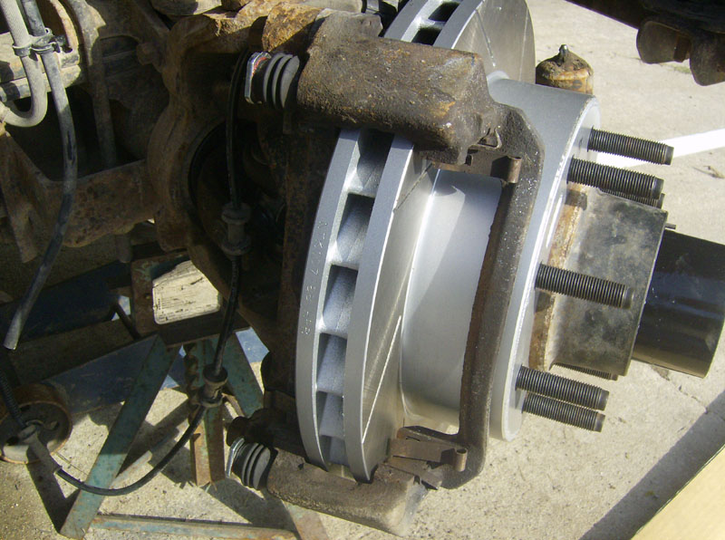
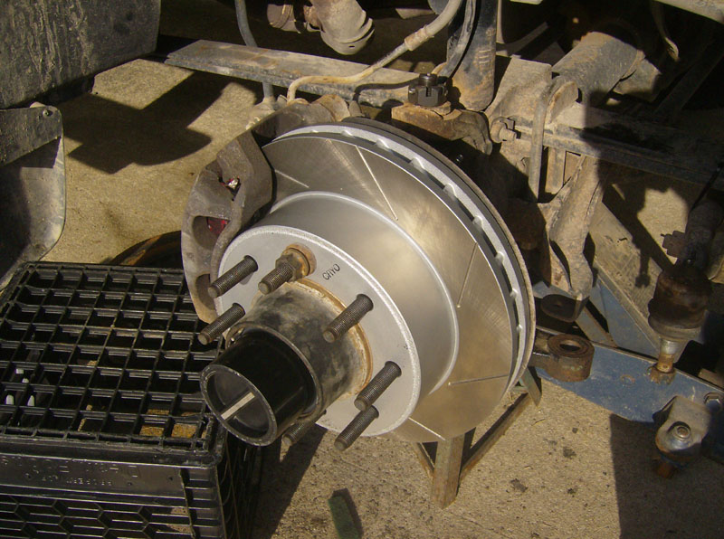
Next, install the brake rotor. Here's the new Powerslot Cryo rotor that I installed. Use one lug nut to hold the rotor in place until everything else is installed.
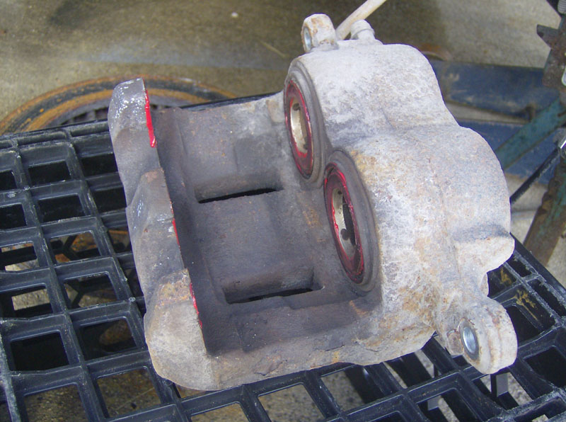
At this point, I did the caliper slide pin upgraded as detailed on Guzzle's site. To see my pics of this process, click here. It would at least be a good idea to remove the pins, clean them up, and grease them to keep them from sticking.
Reinstall the caliper bracket as shown below.
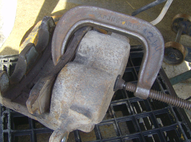
Since I installed new rotors and new pads, the calipers needed to be compressed so that they were fully open. I used an old pad and a c-clamp.
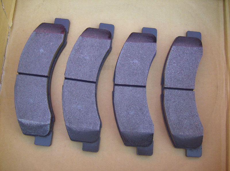
Here's the Hawk pads I used.
Apply a thin layer of caliper grease (included with the new pads) on the areas top & bottom where they'll slide. Then, install the pads on the caliper bracket as shown.
Apply a layer of caliper grease to the backsides of the brake pads.
Install the two spring clips to the brake pads.
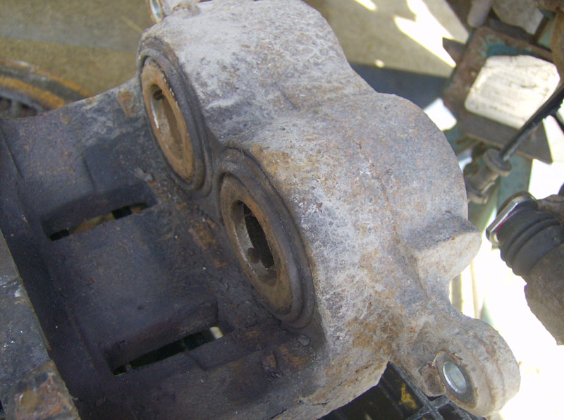
Apply a layer of caliper grease to all the contact points on the caliper.
Finally, install the caliper. Make sure the ends of the slide pins seat into the caliper properly, so that everything lines up. Install the two bolts that hold the caliper on.
Reconnect the tie rod end to the knuckle. Torque the nut to 50 ft-lbs and install a new cotter pin. If it begins to spin before getting tight, you might need to briefly hit it with an impact wrench to seat it. I had to do this on the passenger side, but not the driver's side.
All that's left is to reconnect the ABS wiring, the vacuum hose, grease both ball joints, reinstall the wheel/tire, and test everything to make sure 4x4, brakes, etc still work. Also, bed-in the brakes if they're new. After driving my truck for about 100 miles, I re-checked all the bolts/nuts to make sure everything was still tight.
For the Hawk pads, the recommended bed-in procedure is:
(From tirerack.com)
Make 6 to 10 stops from approximately 35 mph with moderate pressure.
Make an additional two to three hard stops from approximately 40 to 45 mph.
Do not allow the vehicle to come to a complete stop.
When completed with this process, park the
vehicle and allow the brakes to cool completely before driving on them
again. Do not engage the parking brake until after this cooling process
is
compete.
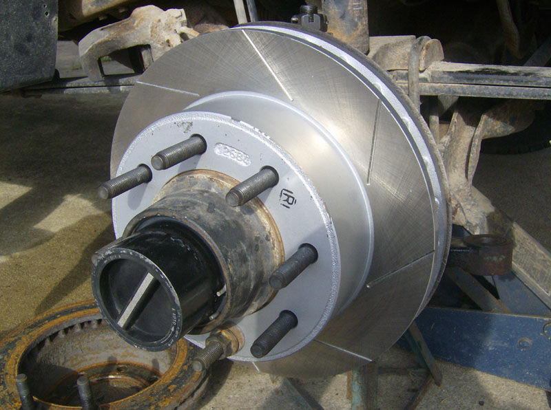
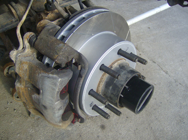
Finally, a shot of the finished job.
Questions or Comments? Email jmray@frontiernet.net