
Ford Super Duty Truck Cap Rear Wiper
2004 F250 4x4 XLT Sport
July 2008
Click Here for a PDF version of this article
I like the top that I have on my truck, but its really annoying not being able to see out of the back glass while driving on wet roads, particularly on the salty wintery roads. So, what would really be nice is a rear wiper/washer similar what every SUV on the road has. After a web search I didn't find any great aftermarket solutions.
There is one kit that has been developed with the truck cap manufacturers as the target customer. That is, this kit has the motor mounting through the glass, which the end users cannot do since the glass is tempered. The truck cap manufacturers can have the glass drilled appropriately, before tempering. This company does offer another kit that has the motor mounted to the wide metal section, at the bottom of the glass. This is a decent solution except having the motor mounted at the bottom of the glass is somewhat undesirable, at least to me.
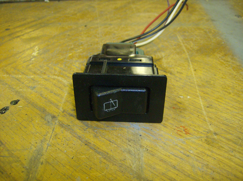
So, since my particular truck cap has a lot of space above the glass, I decided to try to retrofit a rear wiper/washer system from of a 1991-1994 Ford Explorer. I chose this setup, mainly, because I own a 1994 Explorer which allowed me to get good measurements of the wiper arm, swipe area, etc so I was fairly confident that I could make it fit and work. I also chose this setup because it is designed to wipe glass of which it is not mounted to. This means that it has a "park" feature that can stow the blade off of the glass when not in use. Also, the Explorer setup is very simple to wire as it only needs two powers and a ground, since the solid state controller (for parking) is internal to the motor. Finally, a very minor thing, but the early Explorers have the wiper/washer switch on the dash (as opposed to the turn signal stalk) so adding it to a different dash is much easier and gives a very clean look.
** UPDATE NOVEMBER 2008 **
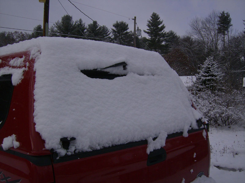
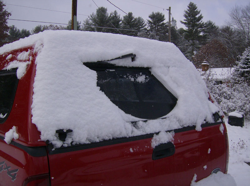
I thought I'd give a quick update since its been about four months since I installed this wiper setup. This thing has worked out great! Everything is holding up really well and it seems like I use it on a daily basis. We just recently got our first decent snow of the season and I snapped a couple pics that are at the bottom of this page.
Also, I found while driving in the rain that it would be nice to have this wiper operate on an interval. So, I came up with a circuit to put inline with the wiper motor signal to either operate continuously or on a selectable delay interval. More info about this at the bottom of this page.
Tools & Parts I Used
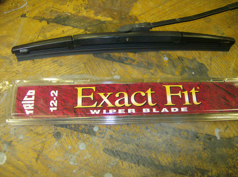
- 12" wiper blade that fits the 1991-1994 Explorer wiper arm
- Pushbutton switch
- Dremel Tool & cutoff wheels
- 12 volt battery, test leads, clamps, cardboard, sharpies, etc (for mock-up)
- Misc power tools - drill press, bandsaw, bench grinder
- Measuring tools - tape measure, digital calipers, 12" ruler, calibrated eyeball
- 1" and 1-1/8" hole saws
- Some wire and cable ties
- Soldering iron, solder, and heat shrink tubing
- Multimeter
- Tube of clear silicon RTV
- 12-24 x 1-1/2" long pan head machine screws
- Small O-rings
- Basic hand tools - screwdrivers, wrenches, pliers, etc
- Misc materials - cardboard, plastic, rubber sheet, metal, etc
- Misc hardware - screws, bolts, nuts, washers, spacers, etc
Here are the parts needed for the delay circuit
| Component | Part Number |
| 2-pole 6-position rotary switch | Digikey # GH5602-ND |
| Switch knob | Digikey # GH7335-ND |
| Blank prototyping board | Radio Shack # 276-150 |
| +5V voltage regulator | LM7805, Digikey # LM7805CT-ND |
| Tantalum capacitor 0.1uF, 35V (x2) | Digikey # 478-1831-ND |
| Tantalum capacitor 1.0uF, 35V (x2) | Digikey # 478-1835-ND |
| Electrolyic capacitor 470uF, 16V (x2) | Digikey # P5141-ND |
| 555 timer IC LM555 | Digikey # LM555CNNS-ND |
| 4.7k ohm resistor | Digikey # 4.7KQBK-ND |
| 20k ohm resistor | Digikey # 20KQBK-ND |
| 12k ohm resistor | Digikey # 12KQBK-ND |
| 26.1k ohm, 1% resistor | Digikey # 26.1KXBK-ND |
| 41.2k ohm, 1% resistor | Digikey # 46.2KXBK-ND |
| 86.6k ohm, 1% resistor | Digikey # 86.6KXBK-ND |
| 133k ohm, 1% resistor | Digikey # 133KXBK-ND |
| 178k ohm, 1% resistor | Digikey # 178KXBK-ND |
| 2N3904 NPN Transistor (x2) | Digikey # 2N3904FS-ND |
| Omron Relay (or any relay with 5V coil) | Digikey # Z740-ND |
Note - the part numbers above were correct as of December 2008.
Requirements
- Your truck cap must have a minimum of 6" of interior space above the glass opening.
- To use the measurements provided below, your glass must be 15-1/2" tall.
- You must have moderate fabrication skills, materials, electrical wiring skills, and tools.
Procedure
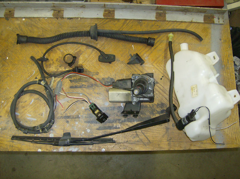
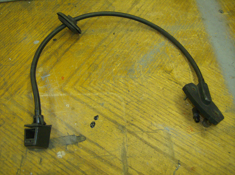
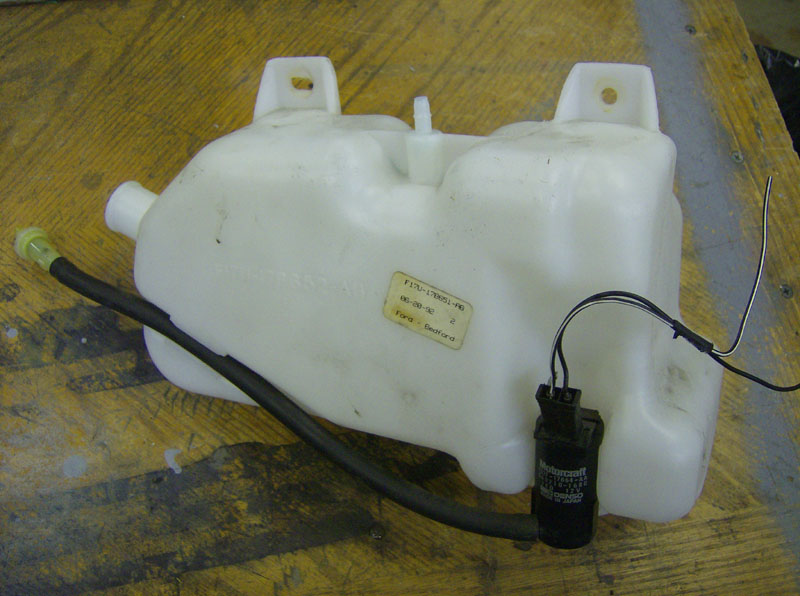
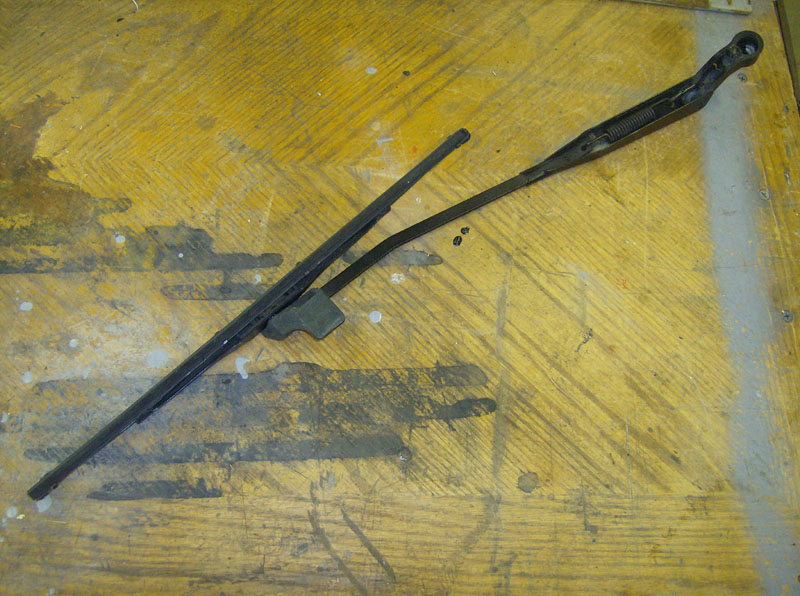
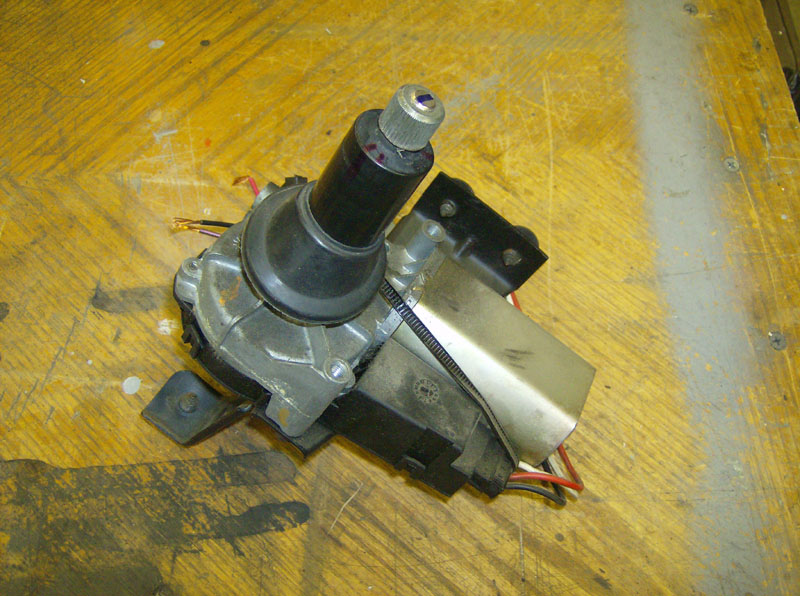
I was able to obtain a complete rear wiper/washer system from a fellow member of The Serious Explorations Forum, thanks Bill! This included the wiper motor, wiper arm/blade, washer tank w/pump, washer nozzle, all tubing, the switch for the dash, and the bracket where the wiper arm rests when not in use.
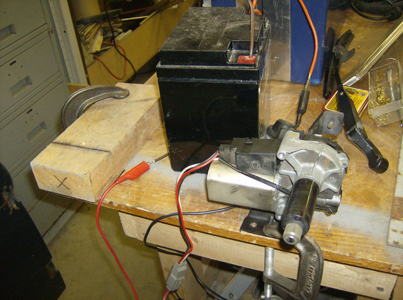
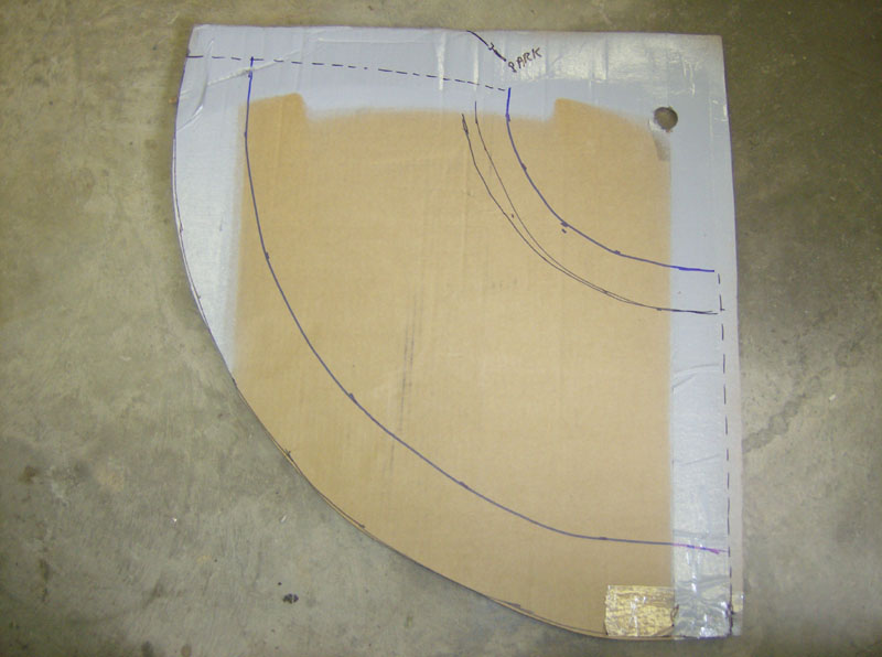
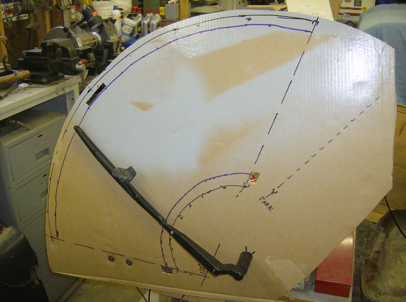
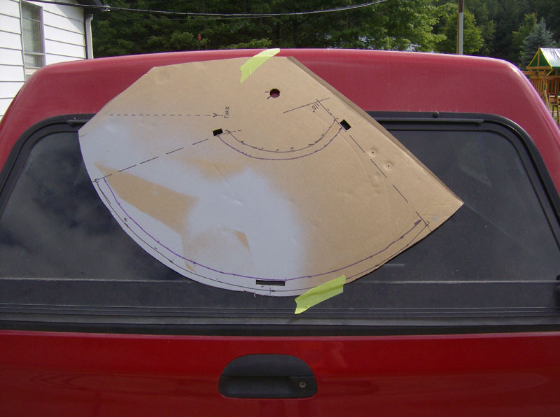
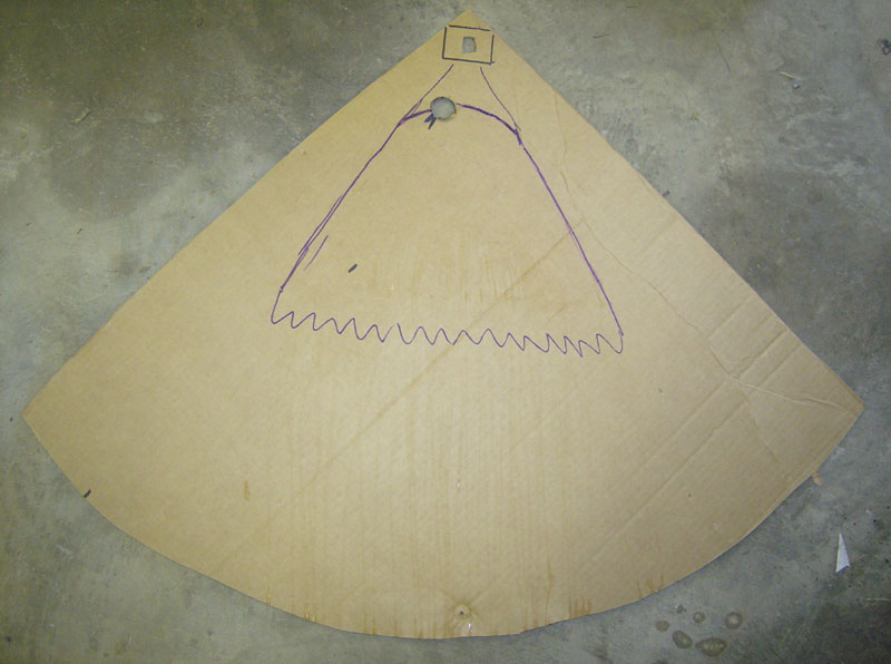
The first thing I did was set up a mock up of the system by clamping the motor to a table and setting up a piece of cardboard to make a template of the wiper pattern and motor location. Its a little hard to tell, but there are two patterns shown. One drawn (roughly) with the black sharpie is the pattern based on the original wiper arm and 14" blade. This pattern turned out to not quite fit on my glass, so I decided to make a second pattern (shown in blue sharpie) based on shortening the wiper arm 2" and using a shorter 12" wiper blade. This pattern fits nicely on my back glass. Note the swipe area is enclosed by the two dashed lines at each end, and the PARK location is shown, considerably away from the wiping area.
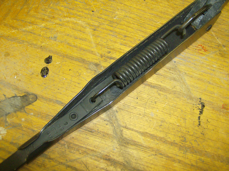
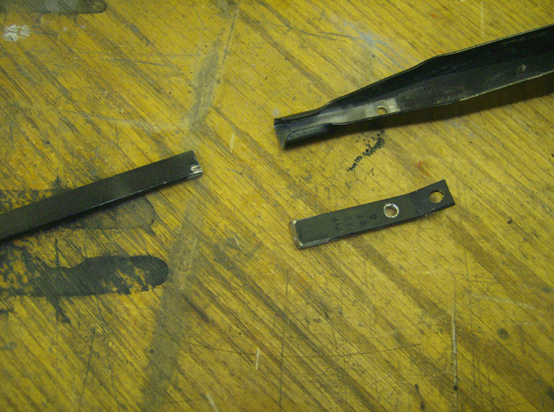
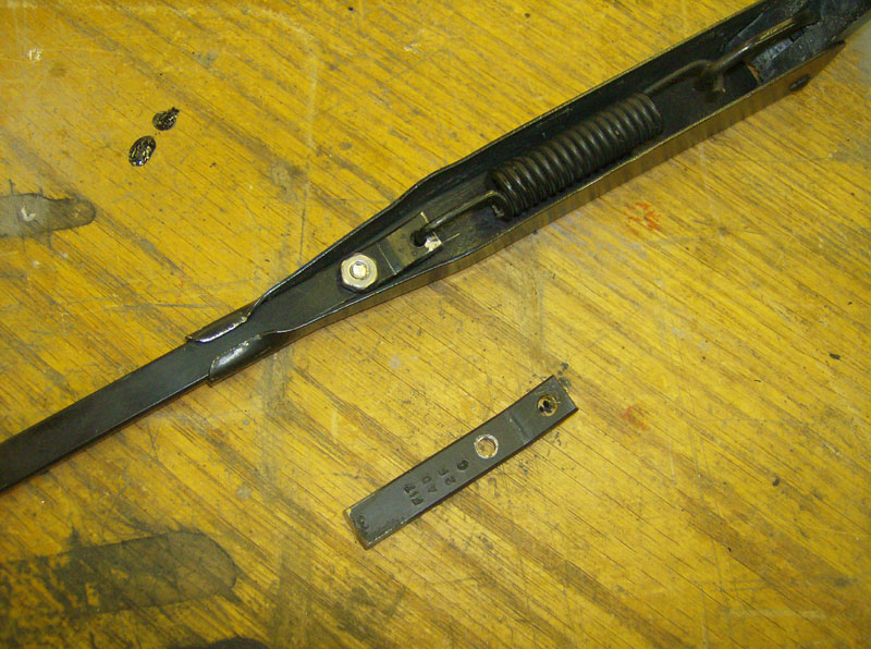
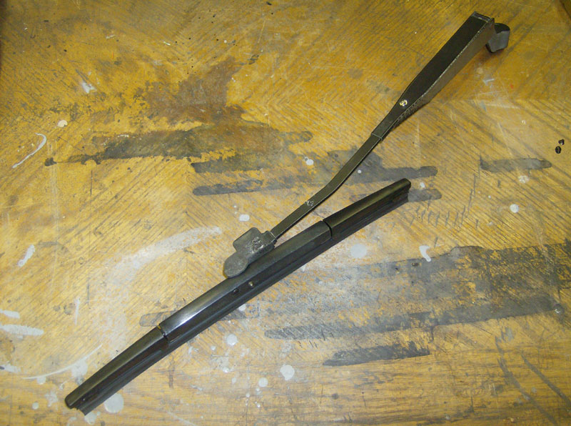
The next step was to shorten the wiper arm by 2". I drilled out the rivet, cut off 2" of the wiper arm, re-bent and drilled to match the original, and put it back together.
Here's the 12" wiper that I found at Advance Auto Parts. It fit nicely on the wiper arm, in place of the 14" blade.
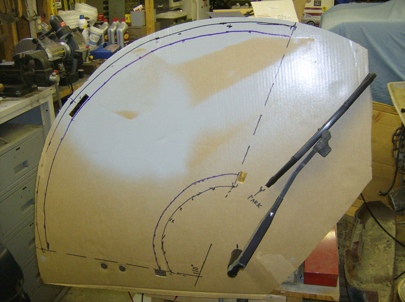
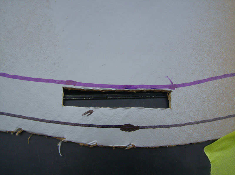
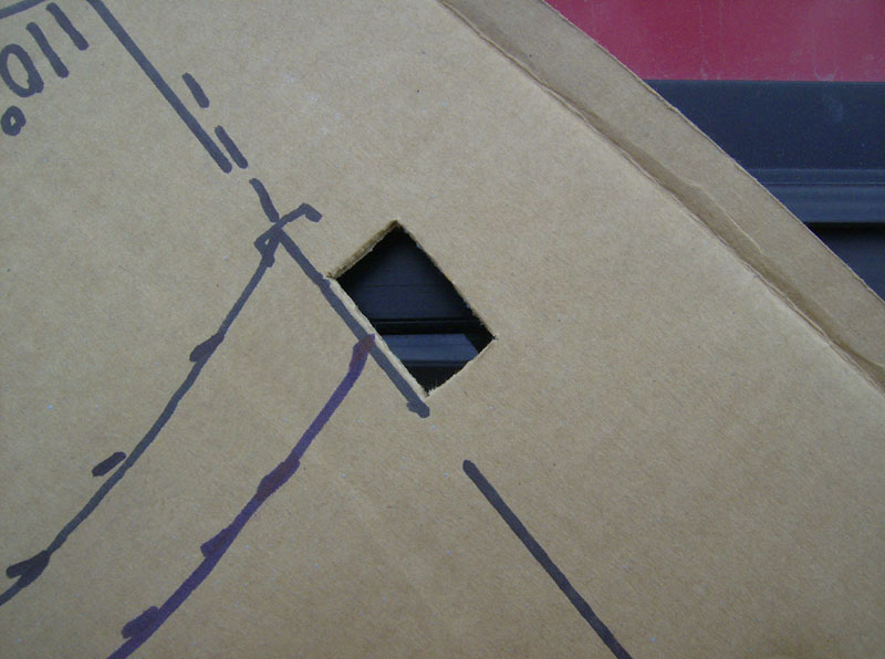
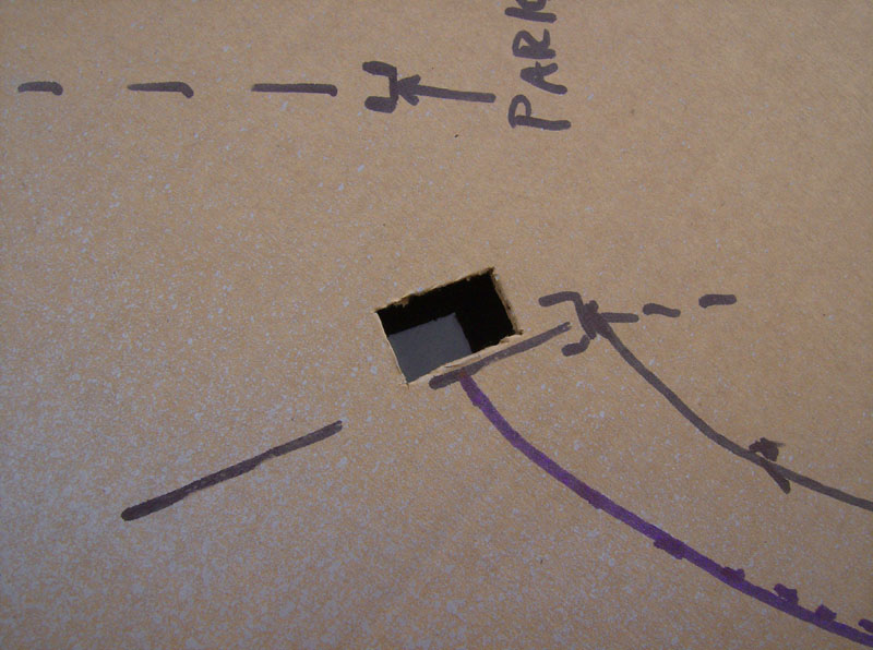
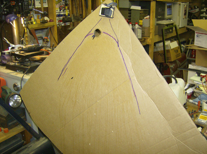
Now that I have the wiper arm shortened, and a 12" wiper blade, I got a different piece of cardboard and made a new version of the template. The black line represents the pattern with the original 14" wiper blade and the purple line represents the pattern with a 12" wiper blade. You can also see three "windows" I cut in the template so I could see through it when sizing it up on the truck.
Here's where I sized it up on the back of the truck.

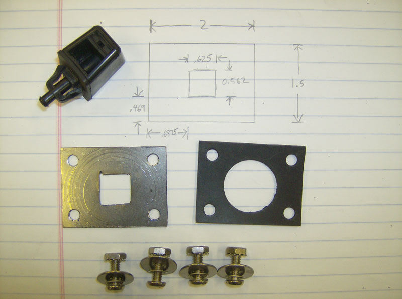
I made a template to use when drilling the holes for mounting the motor.
After many, many measurements, templates, mockups, patterns, measurements, test fits, trial runs, drawings, pictures, and measurements... I finally got the guts to mark and drill a hole in the top. I used a 1-1/8" hole saw and drilled the hole 4" above the top of the glass, centered left/right. Did I mention there was some measuring involved?


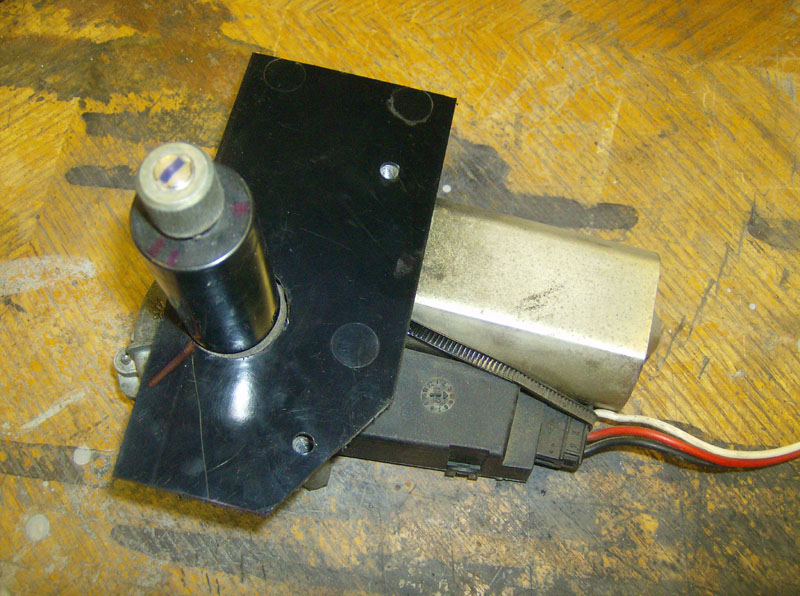
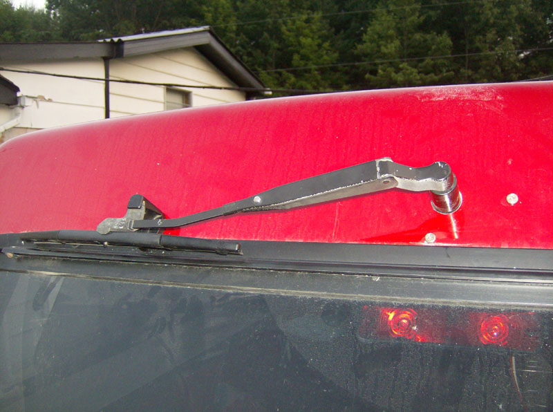
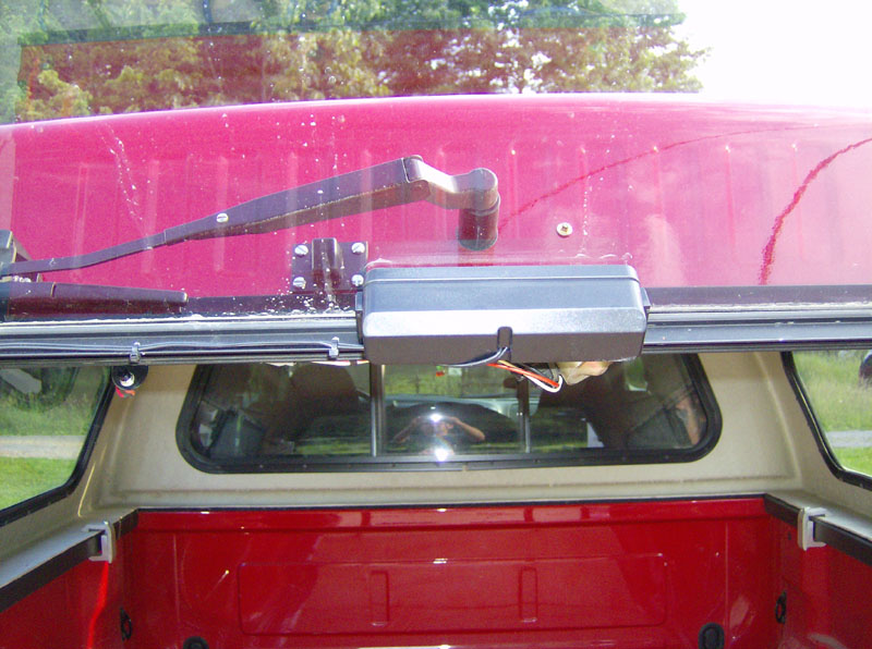
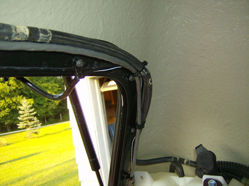
I used the motor hole template (shown above) to locate the two screw holes. I also had to space the motor back a total of 1" (I used 3/4" and 1/4" spacers, see pic below) between the motor and the cap to set the mount height of the motor. The motor has 12-24 threads and I had to use screws that were 1-1/2" long to reach through the spacers. I put small o-rings under the heads of these screws to help seal. I also put a good bead of RTV around the shaft on the inside. Here's a shot of the motor and wiper arm installed.
Here's a shot, from the inside, of the motor. Note the 3/4" & 1/4" spacers, as mentioned above.
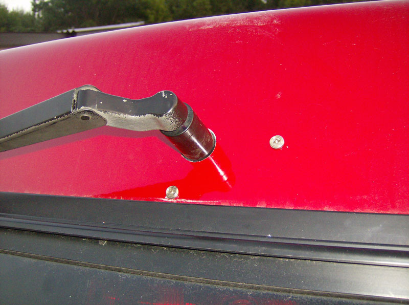
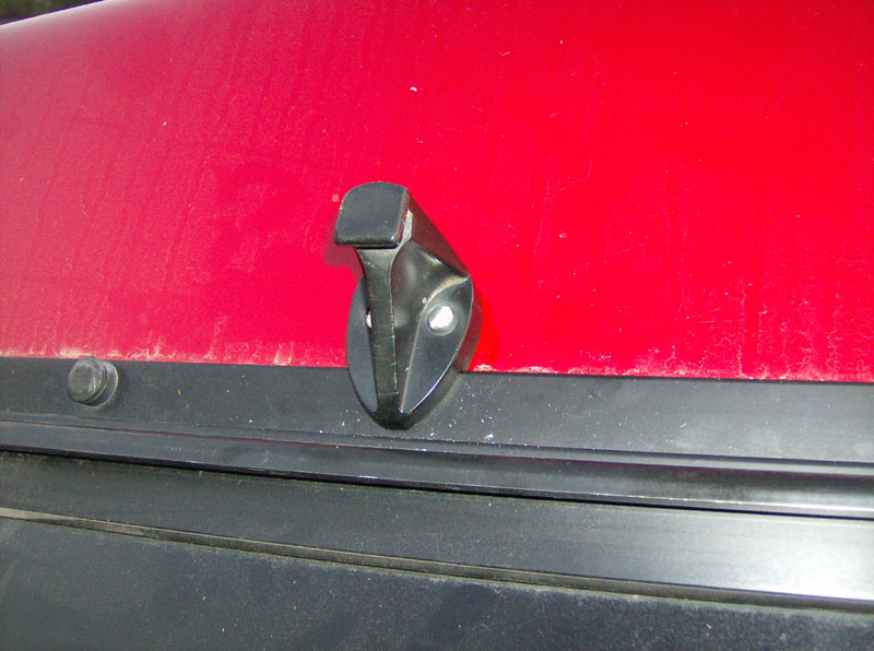
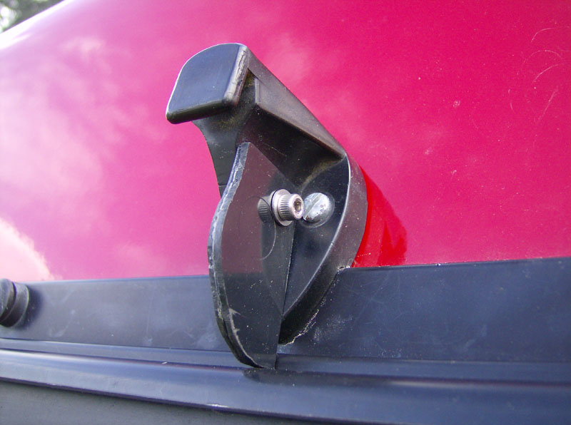
Once the motor was mounted up, I could attach the wiper arm, and locate the wiper arm bracket. Two match-drilled holes in truck cap and the bracket is installed.
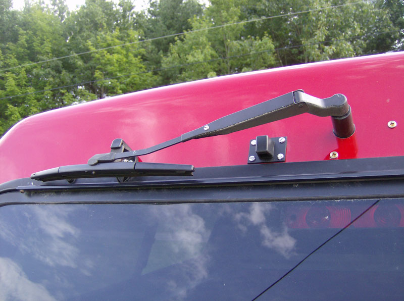
Here's another shot of the motor and wiper arm installed.
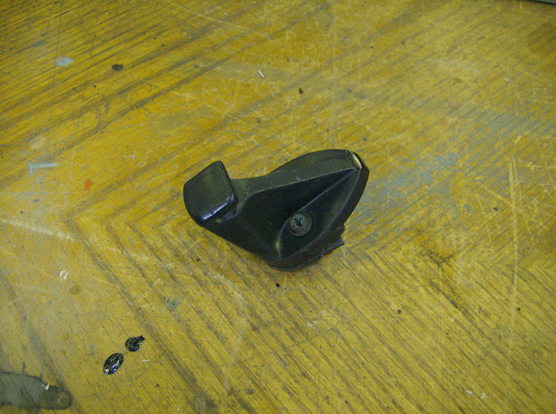
I was having trouble getting it to park properly. The blade would hit the hinge and get stalled on the way up to the bracket. So, I fabbed up a plastic piece to guide it away from the glass on the way up.
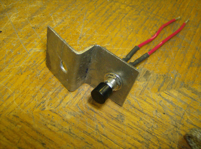
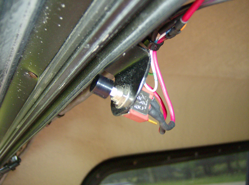
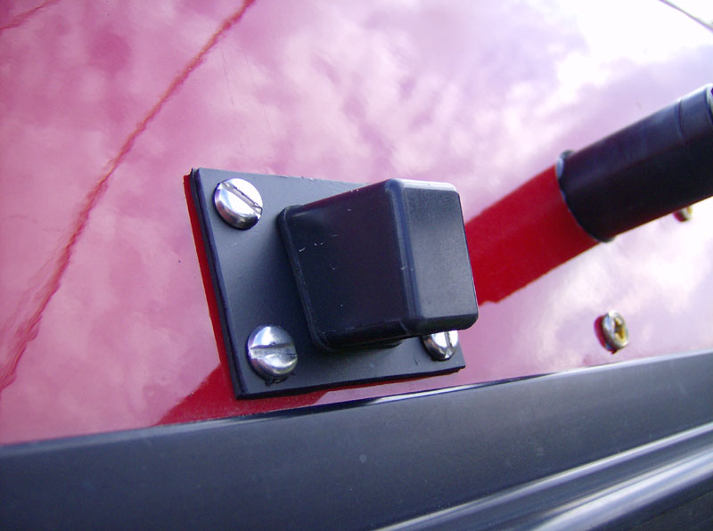
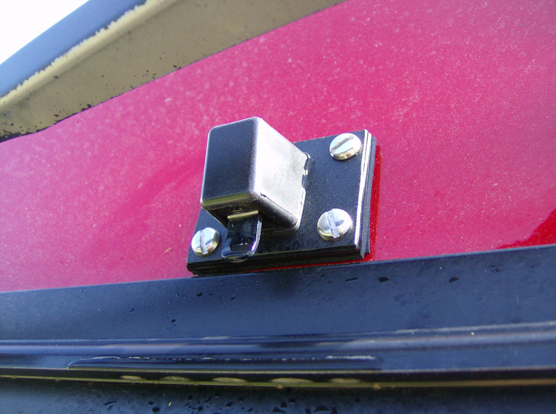
I added a glass position lockout switch for safety. This switch ensures that the wiper motor will not run if the glass is in the up position. At some point I'm going to replace this switch with a magnetic reed switch setup, but this will do for now. I had to fab up a bracket to mount the switch. This switch is normally-open and wired in series with the power to the wiper motor.
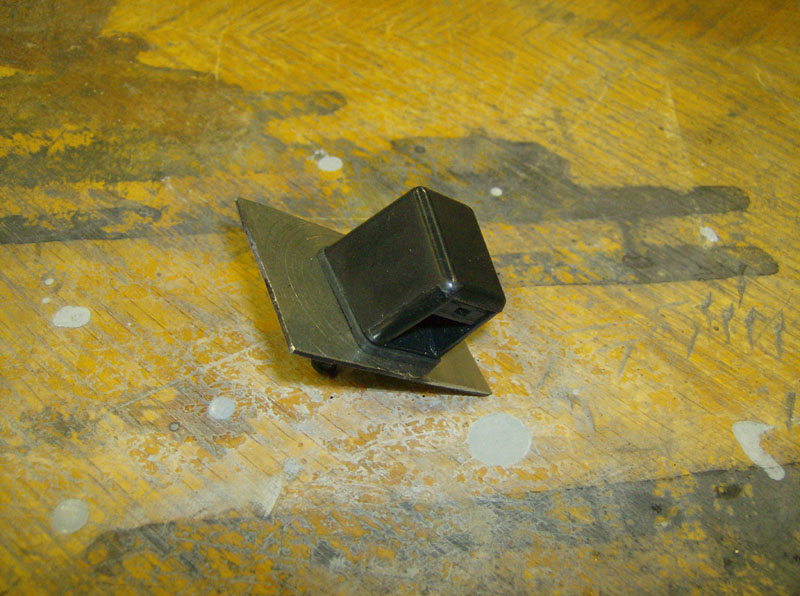
I had to come up with a way to mount the washer nozzle because its designed to mount through sheet metal, which is much thinner than the fiberglass of my truck cap. I just cut a 2" x 1-1/2" x 1/16" thick piece of stainless and cut out the appropriate hole for the nozzle to mount to. I also cut a rubber gasket to seal behind the adapter plate.
Similar to the wiper swipe area, I set up a test pattern for the washer spray coverage. I used this pattern to help me choose where to mount the washer nozzle.
Here's a shot of the washer nozzle installed. I used a 1" diameter hole saw to cut the hole, then I match-drilled four holes for the mounting screws.
Here's a couple shots of the wiper motor, arm, and washer nozzle installed.
After I got the system working, I found that the washer spray was mostly hitting the top of the hinge. So, put in a couple more layers of rubber gasket to space it out, and added a little plastic piece to guide the spray away from the hinge, and onto the glass. At some point I'm going to fab up a spacer block to get rid of that stack of gaskets.
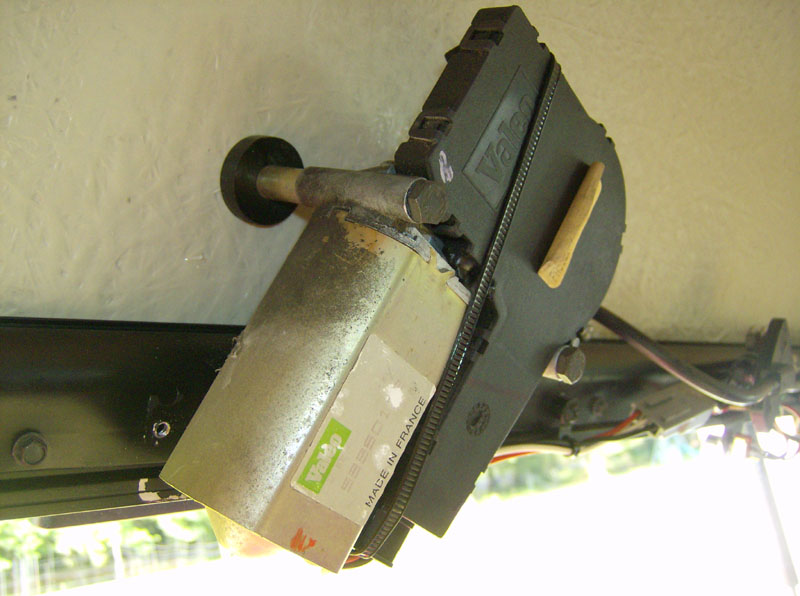
This pic shows how low the motor and glass safety switch hang down.
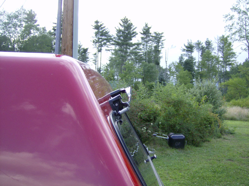
This pic shows how far the wiper system sticks out behind the top.
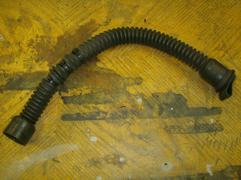
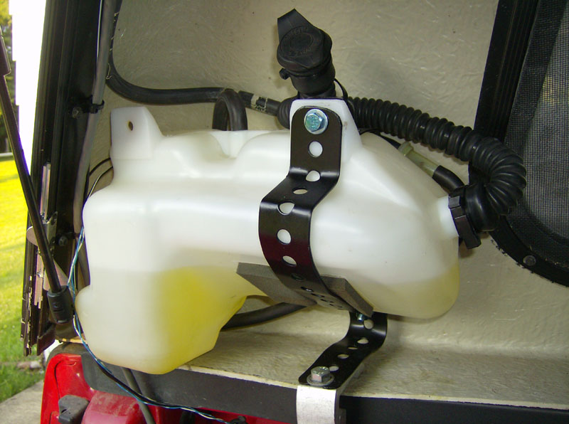
Next thing I did was fab up a mount for the washer tank. I decided to mount it above the bed rail, on the driver's side because that location fit the size and shape of the tank the best. I shortened the original fill tube for the washer tank and cable-tied it to the top of the tank for easy filling.
Here's a shot of how I ran the wiring and tubing down from the motor/washer nozzle area.
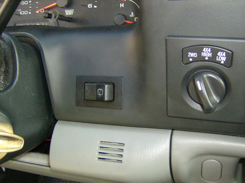
In preparation for cutting my dash to mount the wiper/washer switch, I decided to make a test template to ensure I had the hole size just right.
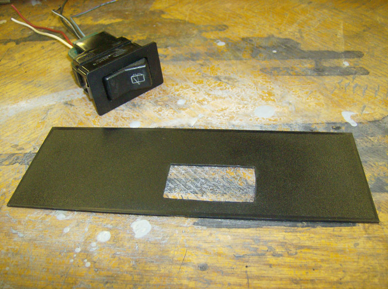
I removed the black dash piece and used the template to mark & cut the hole for the switch.
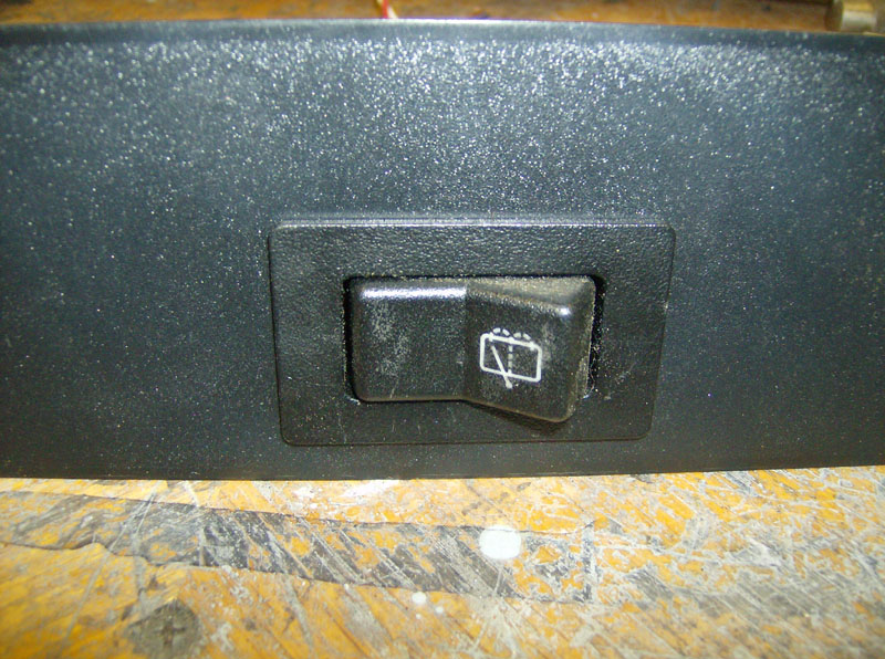
Looks like it was born there.
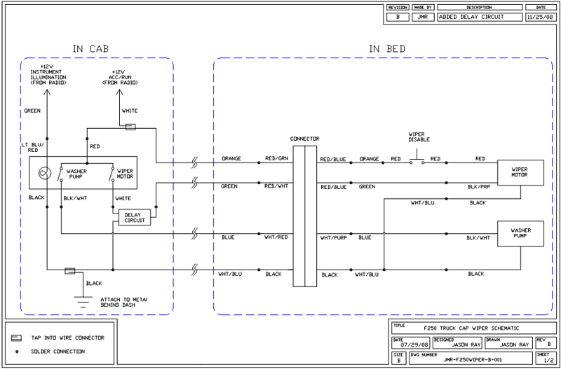
Now for the wiring. Since I had to run four wires from the cab to the back anyway, I decided to run eight wires so they would be in place for future projects. Almost all connections were soldered with heat shrink. The only two exceptions are where I tapped into the "hot in accy" and "ground" inside the cab using the typical inline wire tap connectors. Below is the schematic for this system.
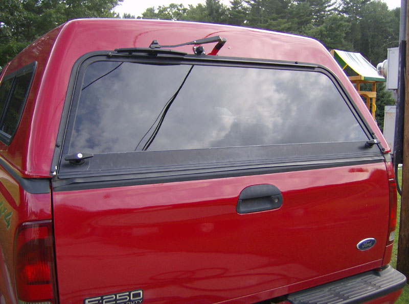
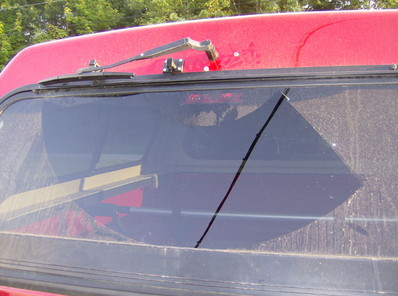
Finally finished. Check out that cleanly
swiped back glass!
Updated November 2008 after our first decent snow since I installed this system...
As mentioned above, I modified the circuitry to allow for a selectable delay interval of 10, 15, 30, 45, or 60 seconds. This involves using a 555 timer chip, a 2-pole 6-position rotary switch, and a relay. The switch selects five different resistor values to adjust the delay of the 555 timer. The timer delay is set to drive high for the duration of the delay, then drive low for a short duration (1.5s) to provide the output signal to the motor (via the relay), to simulate turning the main switch on and off again quickly. The first position of the rotary switch is the "no delay" position and the other five positions enable "delay mode" and select the delay time. The schematic of this circuit is shown below.
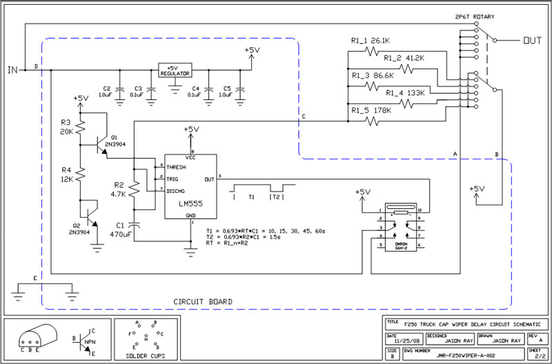
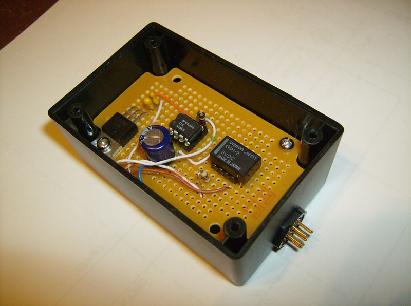
I built this circuit on a small prototyping board and connected it in series with the "IN" wire from of the main switch. Here's a pic of the circuit and the box I put it in.
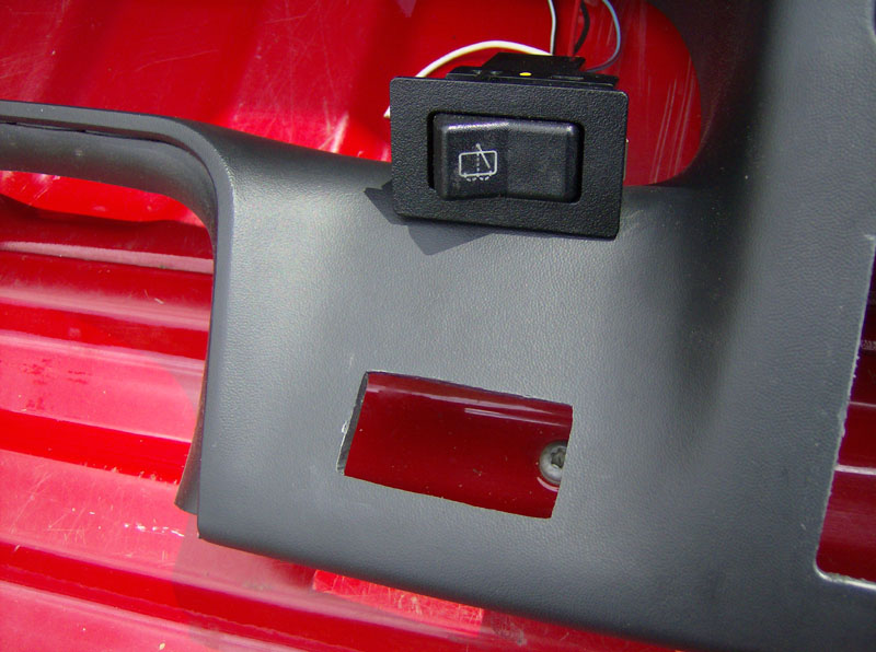
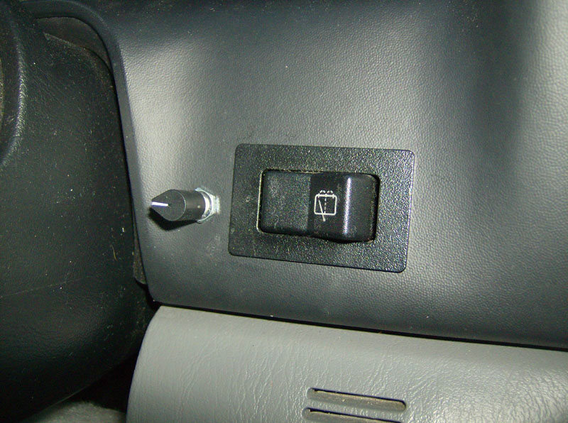
Then I drilled a 1/4" hole to the left of the main switch to mount the rotary switch in the dash. The switch is in the "no delay" position in this picture.
All images and content on this page © 2008 by Jason Ray, unless otherwise noted.
Questions or Comments? Email jmray@frontiernet.net