Ford Super Duty 4x4 Quad Gauge Installation
2004 F250 4x4 XLT Sport Crew Cab
Click here for a PDF version of this article
Click here for info about LED gauge illumination options
Since I bought this truck, in November 2007, I've been thinking about adding some aftermarket gauges to monitor some things that I don't already have in the dash. However, after doing some reading I've found that almost all newer vehicles have glorified idiot lights for gauges. So, I decided to add aftermarket versions of two of the factory gauges along with a few other things.
THE GAUGES
I chose to use Auto Meter Phantom gauges because their price/quality tradeoff seemed to give the best bang for the buck. I would've went for the Ultralite II's except they don't offer a vacuum gauge in that series.
OIL PRESSURE
It turns out that my truck's factory oil pressure sensor is just a switch that causes the gauge to read "normal" whenever the oil pressure is above 6psi or so, according to what I've read on the web. So, I added that to the list of gauges.
TRANSMISSION TEMPERATURE
I've also found that the transmission temperature gauge in my truck is not much better. From what I can tell, it does gradually rise as the temperature rises but it never moves once it reaches "normal". Its basically a real gauge, except its been very de-sensitized. That is, it will indicate when the transmission temperature gets too high, but it doesn't give an accurate picture of the actual temperature, throughout the range. So, I added that to the list as well. Here's a pic I found on the web that shows the operating points of the stock gauge.
![]()
VACUUM
I was researching gauges on the Ford Truck Enthusiasts forum and several users (who have gas trucks instead of diesels) highly recommend installing a vacuum gauge. They report that if you keep a good eye on the vacuum that you can monitor it and adjust your driving style to get better mileage. So, I added that to the list to see how I'm doing.
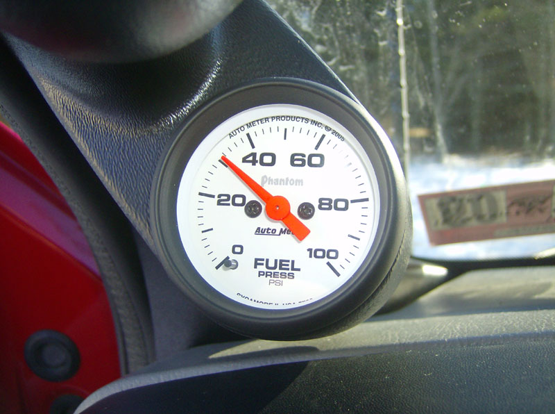
FUEL PRESSURE
Finally, I decided to add a fuel pressure gauge. I know that this is not a particularly important gauge, especially for a stock gasser truck, but I had a fuel pump fail, on my '94 Explorer, at a very inopportune time which caused a lot of inconvenience. So, I'm hoping that this gauge might allow me to catch a failing fuel pump or a failing fuel pressure regulator or some other fuel related problem. We'll see...
REAR DIFFERENTIAL TEMP
While researching gauges on the FTE forum, I got another idea from a few others on there. Several people bought an extra temperature sending unit and used a switched input to the gauge, to allow them to read the rear diff temp on the transmission temperature gauge. So, I bought an extra Auto Meter #2258 sending unit to monitor the rear diff temp.
OIL TEMPERATURE
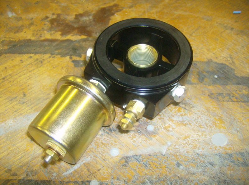
I hadn't planned to monitor the oil temperature but it kind of "fell in my lap" if you will. I was trying to figure out where to connect my new oil pressure sending unit. There's no convenient ports on the motor and it is kind of a pain to TEE into the factory sensor location. I ended up using an "oil filter input adapter plate" that has four 1/8 NPT ports in place to install sending units, oil coolers, oil accumulator systems, etc. Since it has four ports, I figured why not buy another #2258 sending unit and switch it into my trans temp gauge?
TOOLS & PARTS I USED
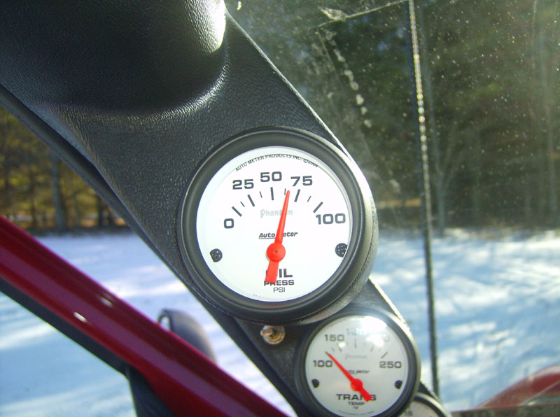
- Auto Meter Phantom # 5727 electric oil pressure gauge
- Auto Meter Phantom # 5763 electric fuel pressure gauge
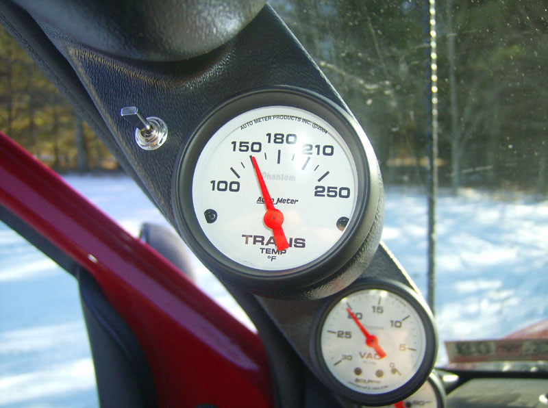
- Auto Meter Phantom # 5757 electric transmission temperature gauge
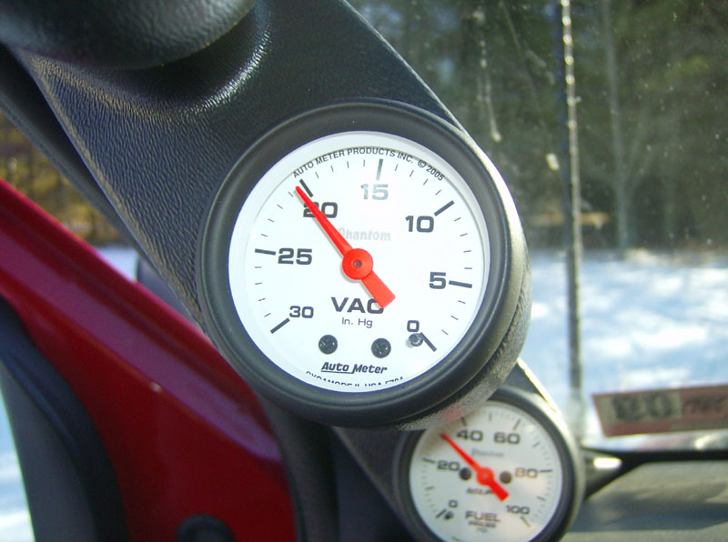
- Auto Meter Phantom # 5784 mechanical vacuum gauge
- Auto Meter # 2258 temperature sending units (2 additional)
- Auto Meter # 3280 fitting adapter
- Brass 1/4" MIP TEE (Lowes)
- Brass 1/4" MIP, 3/8" barb fitting (two of these, Lowes)
- Brass 1/4" MIP, 1/4" barb fitting (Lowes)
- Small hose clamps (two of these)
- Glowshift # GS-AF5 M22-1.5 oil sender adapter plate
- Mag-Hytec Ford 10.5 rear differential cover
- Single Pole Three Throw (SP3T) switch, Digikey # 360-1855-ND
- Various colors and lengths of 18AWG stranded hookup wire
- Misc spade connectors
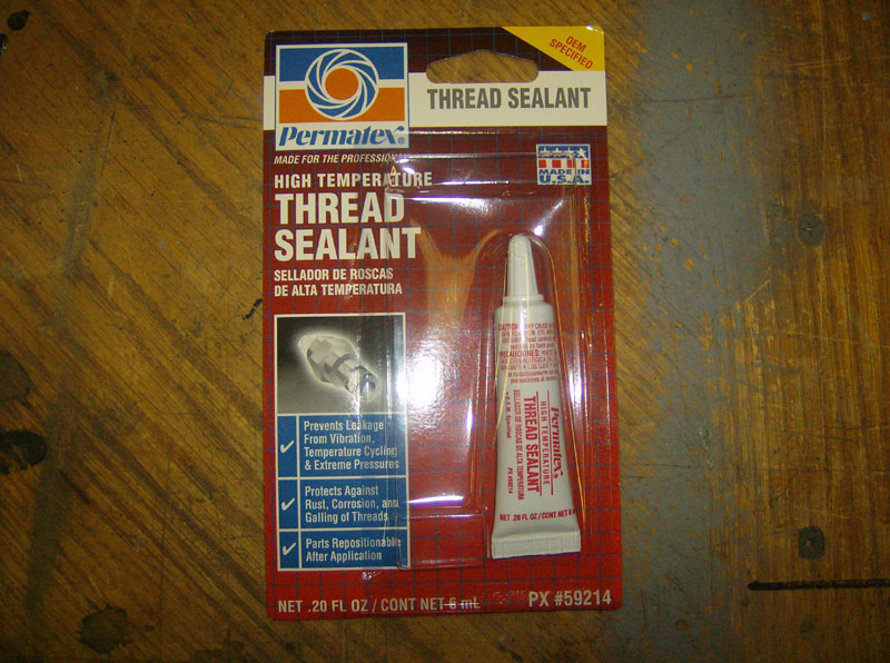
- Permatex High Temperature Thread Sealant #59214
- Teflon tape
- 1/4 drive ratchet, 3" extension, and 8mm socket (grab handle).
- Typical standard & metric wrenches, nutdrivers, etc.
- 11/32" wrench (schrader valve)
- Stubby phillips screwdriver
- Soldering iron & solder
- Various sizes of heat shrink tubing
- Cordless drill and bits
PROCEDURE
I started by installing all of the sending units and then the wiring. The first of which being the oil pressure and oil temperature senders. Here's a pic of the oil filter adapter plate with the sending units installed.
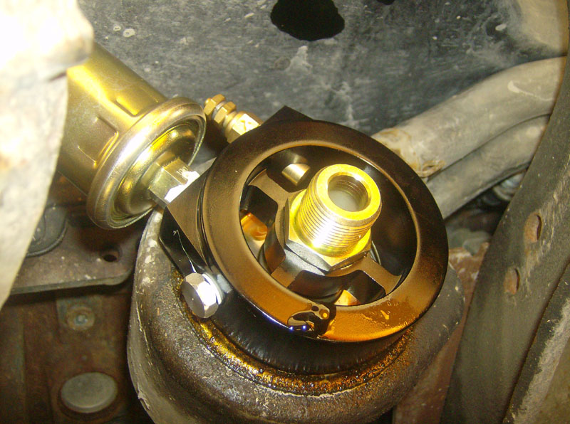
Then I installed this assembly, along with a new oil filter.
Next, I installed the transmission temperature sender into the transmission "test port" on the driver's side of the 4R100 transmission. This port is a 1/8" NPT threaded hole with a plug in it.
![]()
Its as simple as removing the plug and installing the sending unit, with teflon tape.
![]()
I had intended to use a sending unit manifold tapped into the front-most (outgoing) cooler line coming out of the transmission. I wanted to tap into the outgoing fluid so that I was monitoring the worst-case temperature to catch any overheating problems as early as possible. Since I was doing this in the middle of winter, I didn't want to cut into my transmission lines and risk crippling my truck in case the weather got bad. Depending on the results with the test port, I might move the sender this spring.
The next one I installed was the fuel pressure sender. This was a fairly easy install since my truck has a schrader valve on the fuel rail. After using a fuel pressure gauge to de-pressurize the fuel rail, I removed the schrader valve with an 11/32" wrench. Then I installed the Auto Meter # 3280 fitting adapter on to the sending unit. I used the permatex high temperature thread sealant on all of these threads because the instructions advised against using teflon tape here.
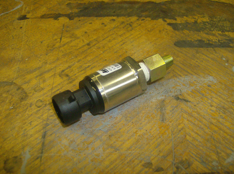
Next I installed the sender where the schrader valve used to be.
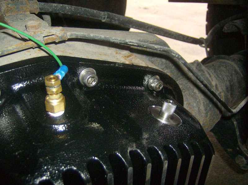
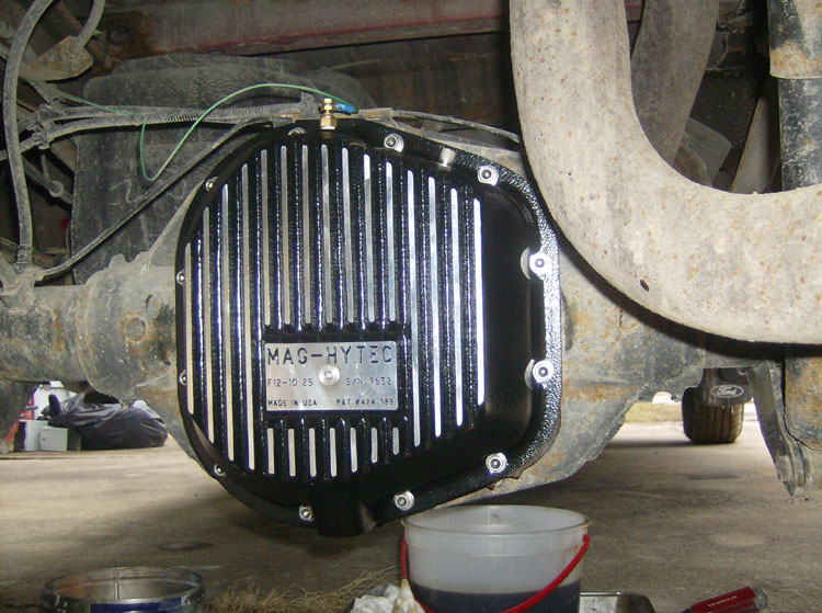
The next one I installed was the rear differential temperature sender. This would usually involve removing the cover and welding in a 1/8 NPT bung into the cover (Auto Meter # 2260). However, "Santa 2008" got me a Mag Hytec rear diff cover which has a built in sending unit port. So, of course this install was a breeze. I also replaced the rear diff gear oil while I was at it. And, of course, teflon tape on the threads!
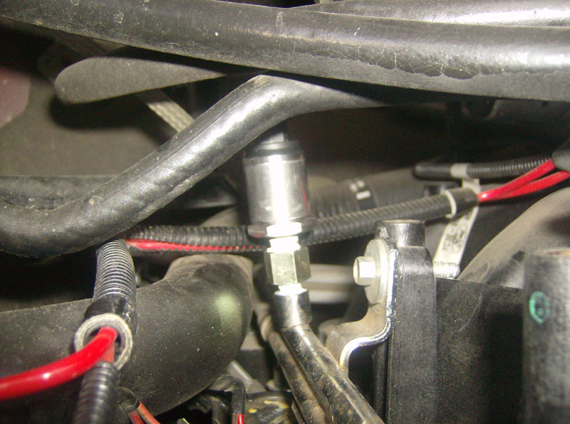
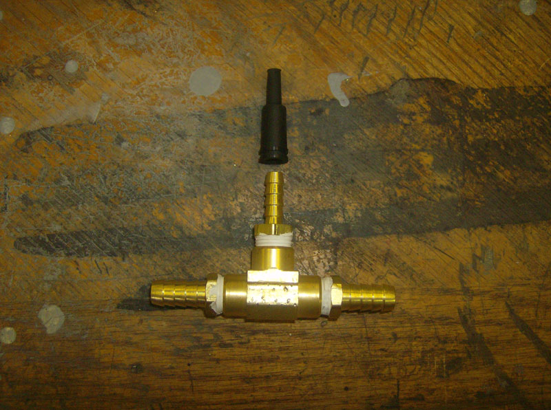
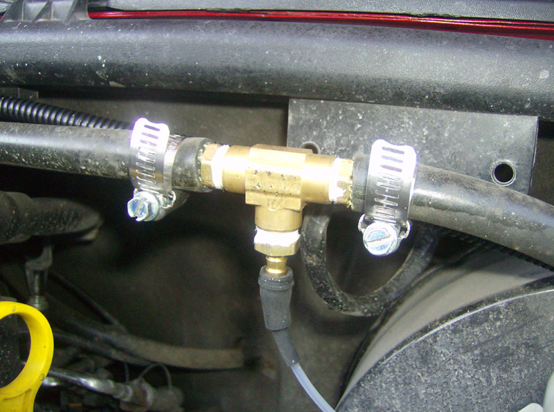
Finally, the last install was the TEE for the vacuum gauge. I TEE'D into the brake booster line to get to the engine vacuum. This was a very convenient place to tap into and it only required a TEE, two 3/8" barb adapters, one 1/4" barb adapter, and two hose clamps. The rubber piece that connects the vacuum tubing was supplied with the gauge.
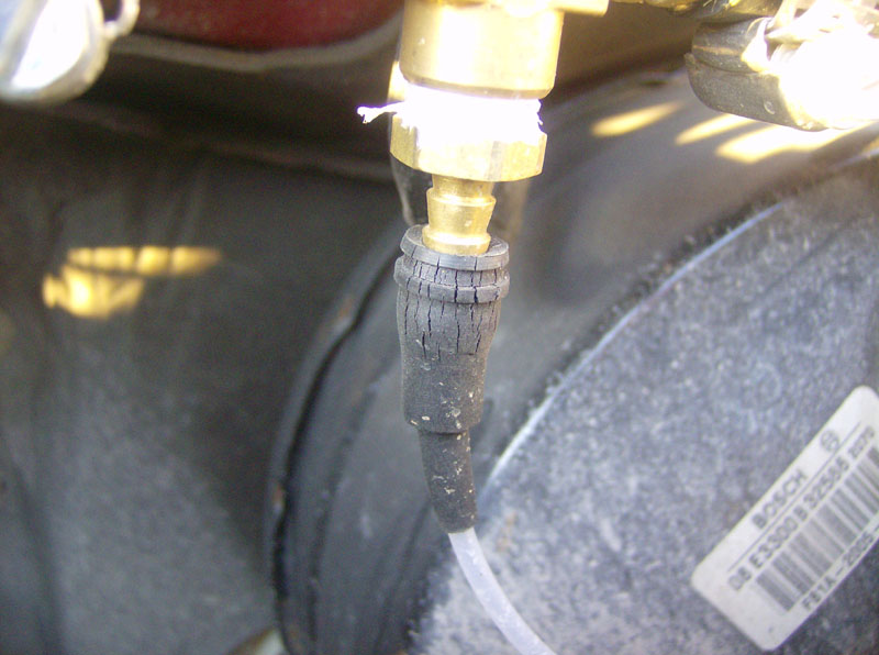
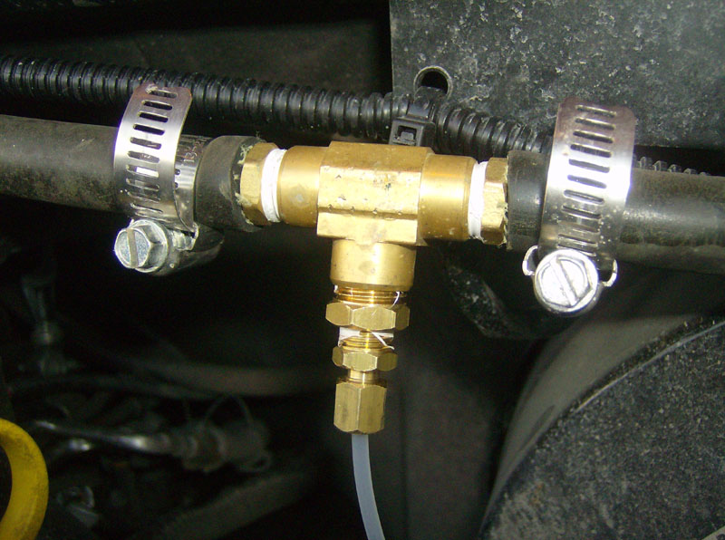
** UPDATED APRIL 2009 ** After three months of use, the rubber fitting shown above became cracked and dry rotted. Auto Meter told me they received a bad batch of these and that a few of them made it into the field. Lucky me. They did send me a new one, but I decided to replace the barb & rubber fittings with a compression type fitting. Should hold up better.
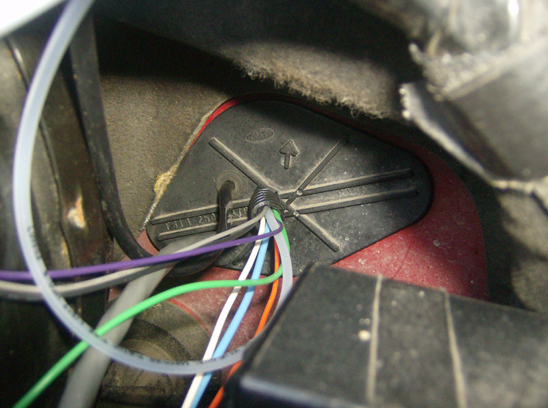
Finally, I ran different color 18AWG wire from each sender, cable tied to existing wiring and the frame rail, up to and through the firewall. I used the same plug that I've used before to get the wiring and 1/8" tubing into the cab. I drilled a 1/2" hole in the plug and used some 3/8" loom to get the wiring/tubing into the cab. Also, I soldered on ring connectors to connect to all sending units.
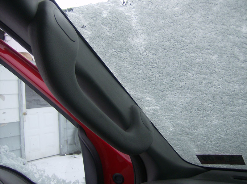
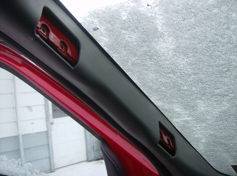
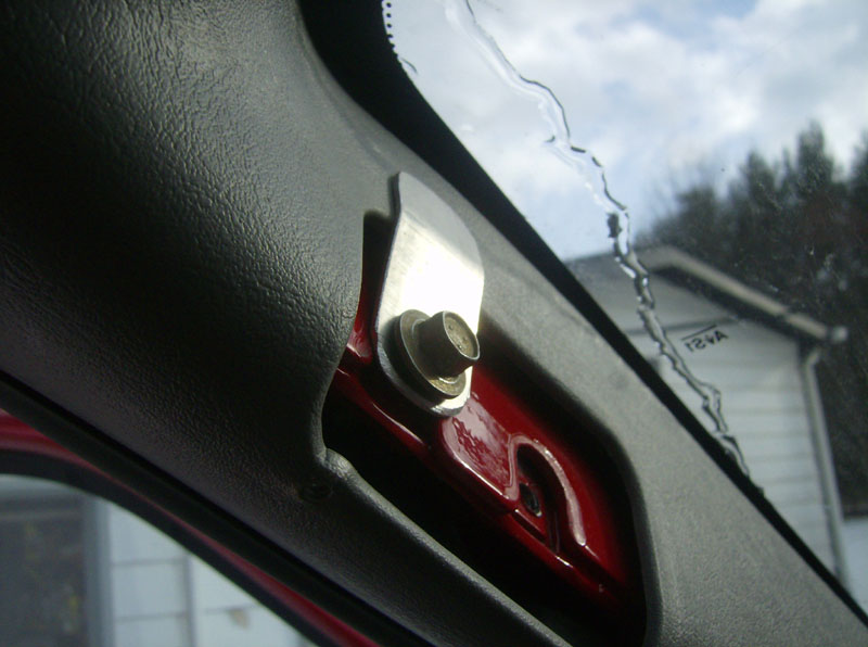
The next thing I did was remove the grab handle on the driver's side pillar. Pop out the two bolt cover plugs and remove the four bolts with an 8mm socket. The handle won't yet come off because there are two phillips screws that come in from the backside of the pillar cover. So, once you pull the pillar cover (just pulls out) away, you can remove these two screws (I used a stubby phillips screwdriver) and the grab handle.
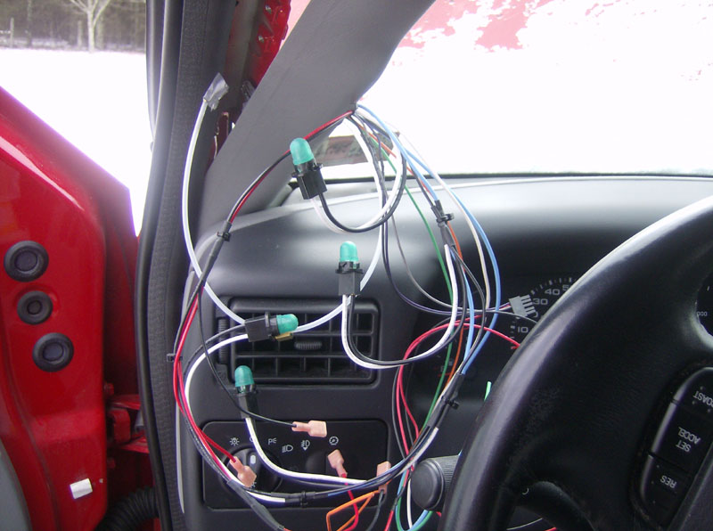
Once inside the cab, I routed all the wires/tubing up to the bottom of the pillar cover. Here's a shot of the rats nest...uh, I mean, wiring.
I had to do some prep wiring on the SP3T switch. One external wire was required to achieve three throws on a single pole switch. I then soldered a wire to the common point on the switch and soldered a spade connector to the other end of this wire. This wire connects to the "S" connection on the back of the transmission temperature gauge. I soldered short wires onto the switch for the three poles. I then soldered these three wires to their respective sending unit wires for trans temp, rear diff temp, and oil temp.
Next, I soldered a spade connector on the oil pressure wire and connected it to the "S" connection on the back of the oil pressure gauge.
Next, I connected the fuel pressure wiring harness to the back of the fuel pressure gauge. Since I didn't want to drill a 1" hole in the firewall, I cut the three wires coming from the fuel pressure sending unit and soldered them back together once inside the cab.
Next, I attached the nylon tubing to the back of the vacuum gauge.
Finally, I drilled a hole in the pillar pod for the SP3T switch and installed it beside the trans temp gauge.
I had prewired the "harness" for the gauge illumination so that part was as simple as plugging each bulb into the gauge. I also prewired the "harness" for the power & ground for the gauges. I soldered spade connectors on these wires and connected +12V to the "I" terminal and GROUND to the "GND" terminal.
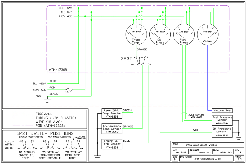
Here's the schematic of how I wired up the gauges
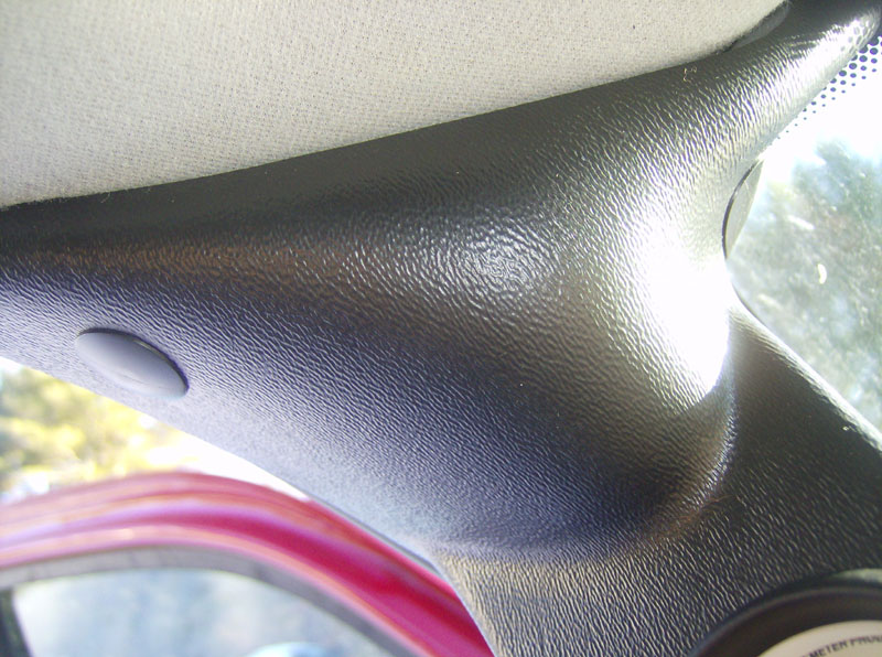
Before installing the pod, I noticed that the top of the pillar cover wasn't as secure as I'd like. It seemed to flop around a bit. So, I fabbed up a small aluminum bracket and used an existing grab handle bolt to secure the pillar cover a little better.
Next was to install the pod onto the original pillar cover. This was as easy as match-drilling some holes in the pod and pillar cover. Then insert the four push in plug connectors to hold the two together. I found that the supplied plugs didn't hold real well at the top of the pod, so I used some bigger ones I had laying around.
Now that all of the wiring has been installed onto the gauges, its time to connect up the power, illumination, and ground to the appropriate places. I connected +12V (in acc/run) to the same wire that I my CB uses. I used an inline fuse holder with a 1 amp fuse for this connection. I tapped into the blue/red wire from the headlight switch for the instrument illumination voltage. Finally, I connected the ground wires to the metal framework behind the dash.
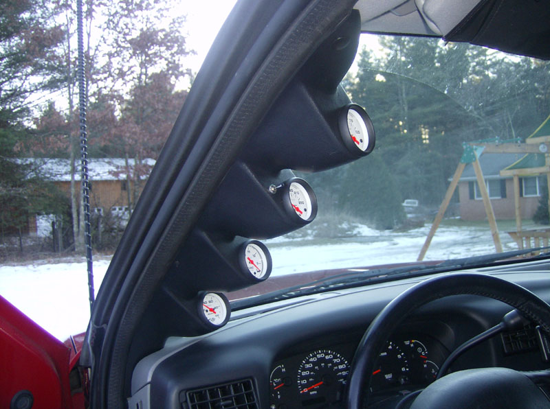
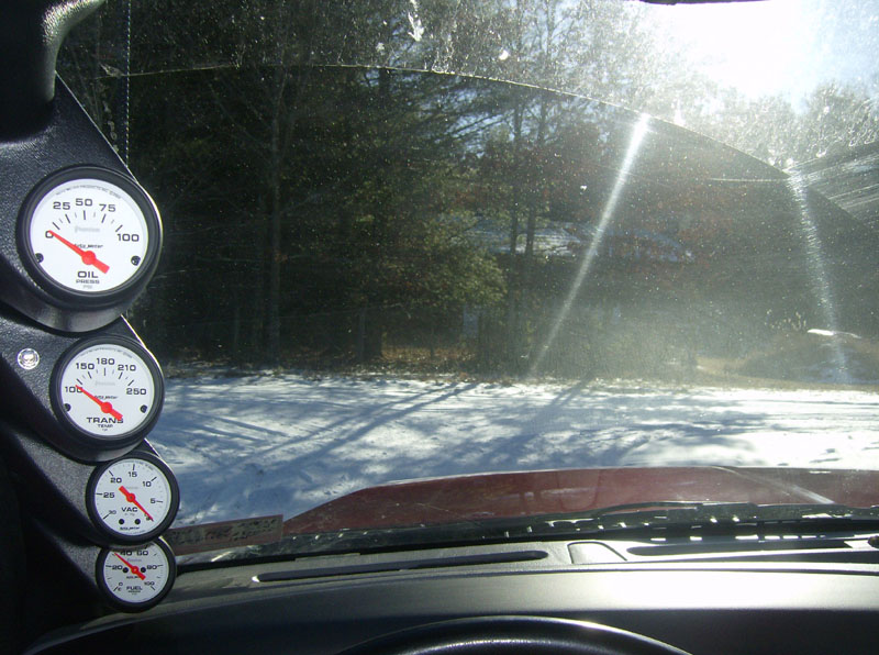
So, here's the finished product. The view isn't really that much more blocked than it was with the grab handle and they are super easy to keep an eye on while driving.
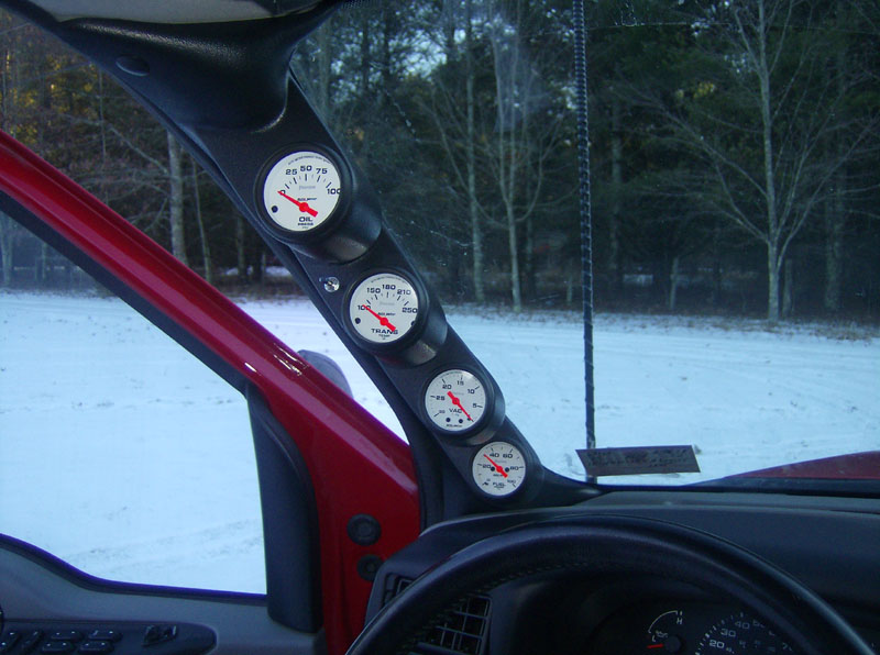
I was totally surprised at how sensitive the vacuum is to driving style. I can see a lot of room for improvement in my driving style as it was reading below 10 for most of my test drive. I'll try to update this page in six months or so to see if I have improved my mileage with this gauge.
=-=-=-=-=-=-=-=-=-=-=-=-=-=-=-= GAUGE ILLUMINATION =-=-=-=-=-=-=-=-=-=-=-=-=-=-=-=
Well, to put it mildly, I was unhappy with the standard illumination of the Auto Meter Phantom gauges. Not only did the four gauges have different levels of brightness, but they weren't all the same shade of green (due to the brightness difference, I assume).
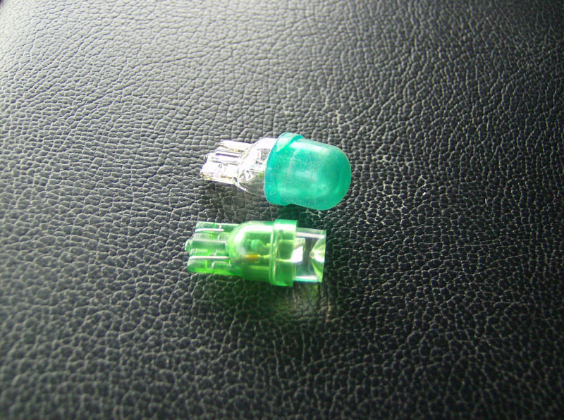
So, I did a little research and found that Auto Meter offers an LED bulb upgrade for these gauges. Unfortunately at around $14/ea (in Feb 2009) it adds up quick when you have four gauges. Given that the bulbs were a standard mini wedge style bulb, I went on a search for an alternate source. I found that superbrightleds.com has these replacement bulbs (part number WLED-G-X, 120 deg beam pattern) in green, for less than $2/ea!
Here's a bulb I got from superbrightleds.com, next to one of the original bulbs.
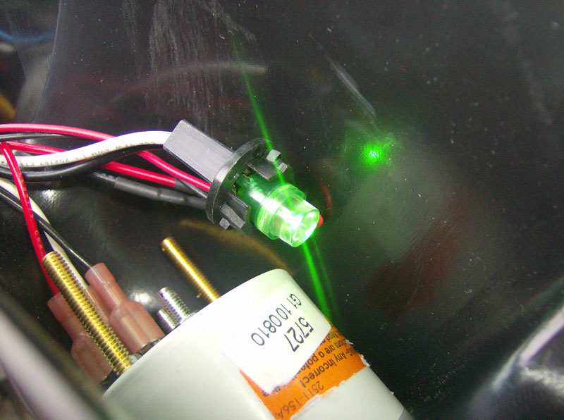
Here's the test fit of the new bulb. You need to test it before putting the pod back in place because these bulbs only work one direction.
Here's the before & after comparison pic. The illumination is much more consistent and full.
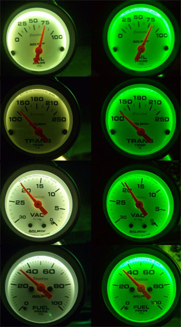
Here's the close-up shots of the comparison for each gauge.
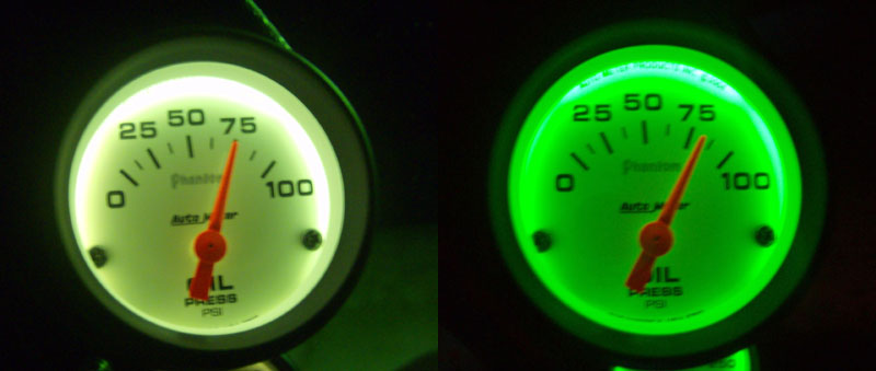
![]()
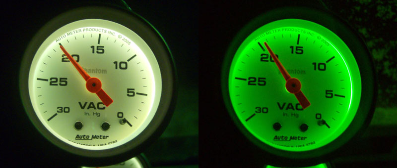
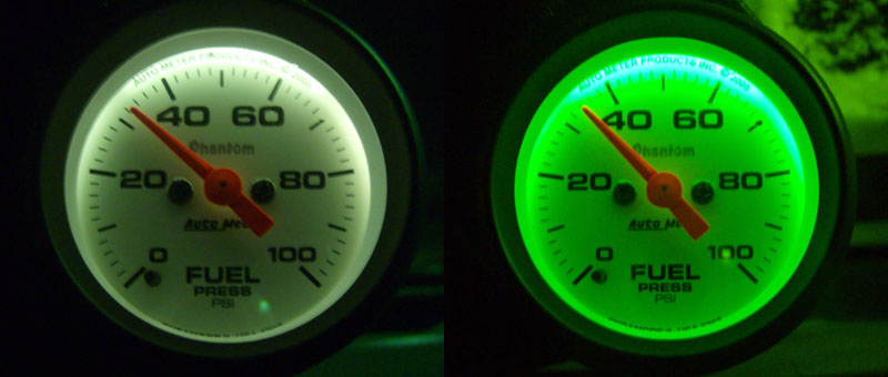
So, you can get this result for less than $8 compared to around $52 for the Auto Meter bulbs.
Questions or Comments? Email jmray@frontiernet.net