6V6 Trainwreck Express in recycled combo cabinet
Evolution of an inexpensive solid state practice guitar
amplifier into a legendary Trainwreck Express
In 2009, my friend and co-worker Gary gave me his old solid
state guitar practice amp, a Peavey Envoy 110. It had
been sitting in a closet, and he wasn't sure it even
worked. I really didn't care if it worked, as I just
wanted a junk chassis and cabinet suitable for tube amp
hacking. I
ripped out its solid state guts, replacing them with a
vacuum tube circuit with a pentode preamp and cathode-biased
push-pull 6V6 output tubes. In January 2015, I began
the next step in its evolution, replacing the tube circuit
with my own take on Ken Fisher's Trainwreck Express design.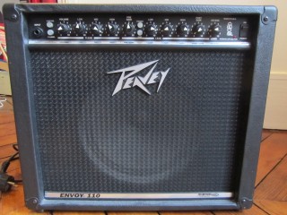 |
 |
 |
 |
 |
 |
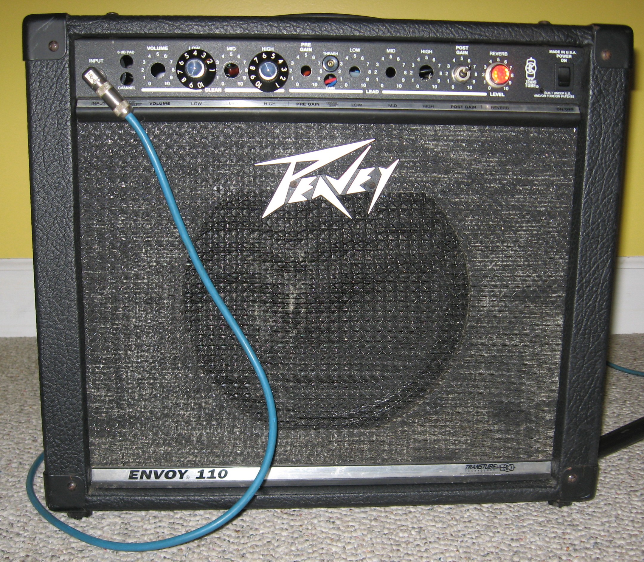
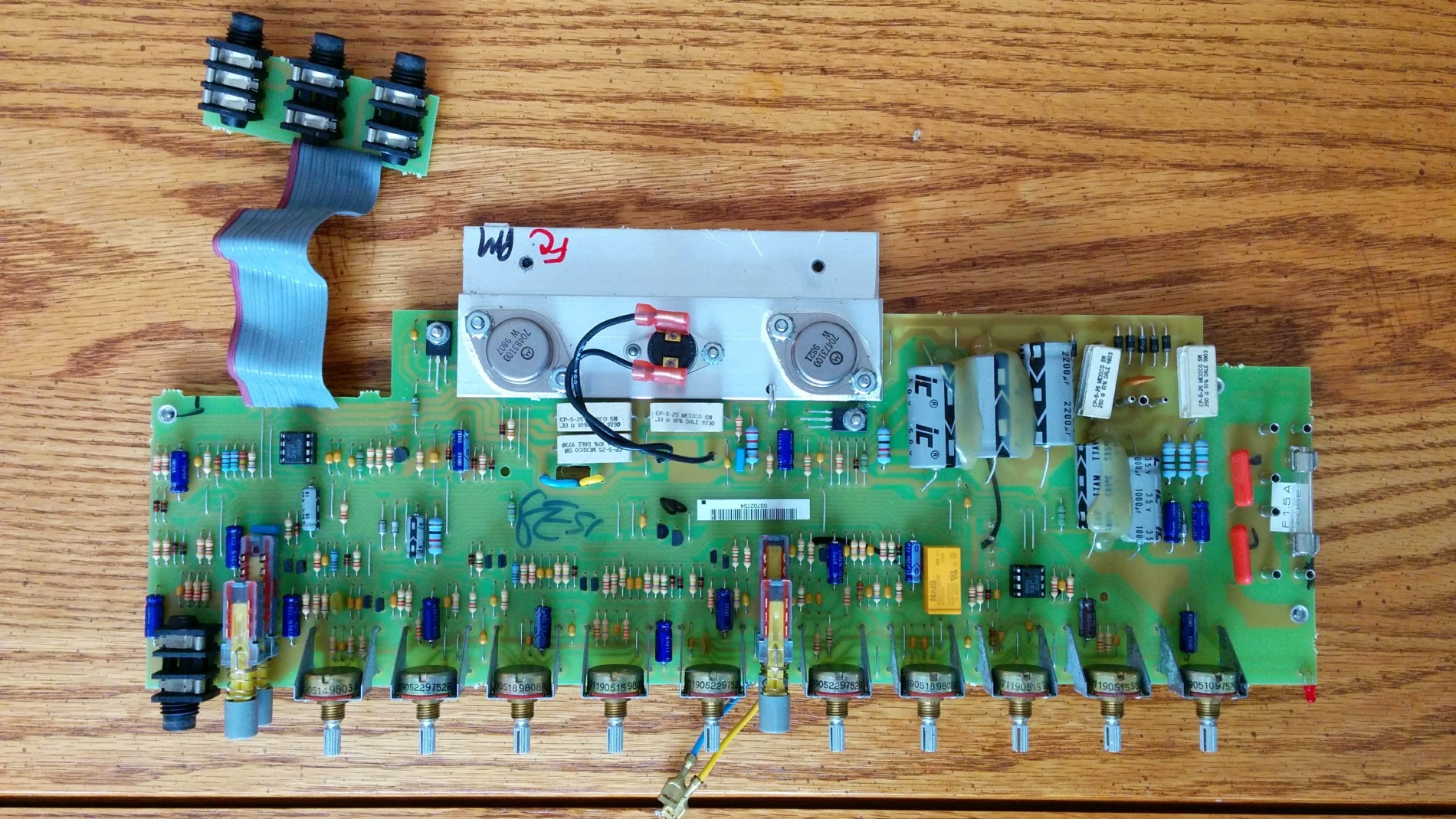
| The amp as it came from the factory
around 1998 or so. Peavey does ok with the
Tolex job, but it's covering cheap MDF.Below is the
original solid state circuit board |
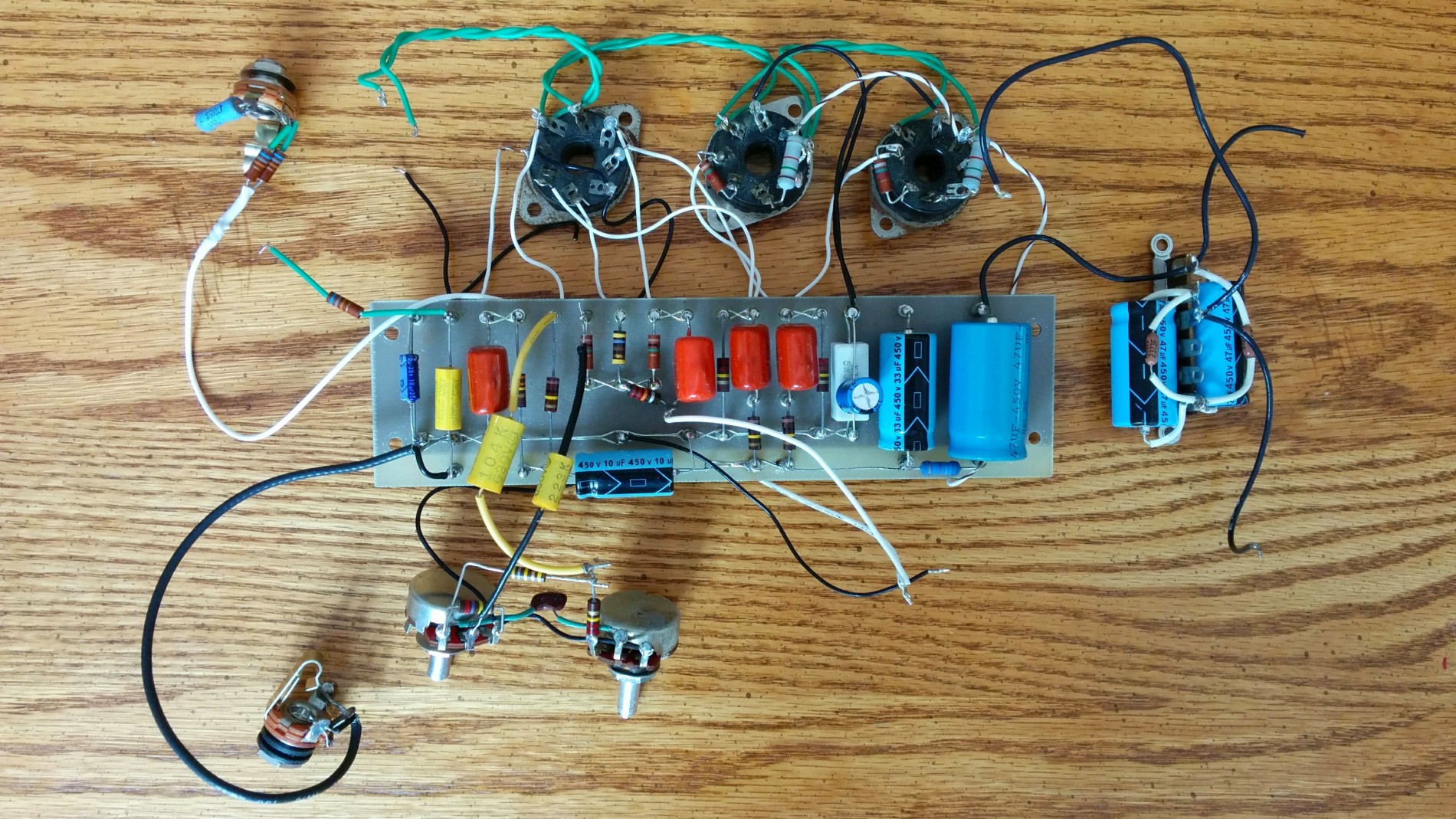
As it appeared after I performed the
first conversion to tubes in 2009. Since this was my hacking platform, I didn't spend any time making it look nice. The circuit board is my Moonlight prototype, now back on the shelf. |
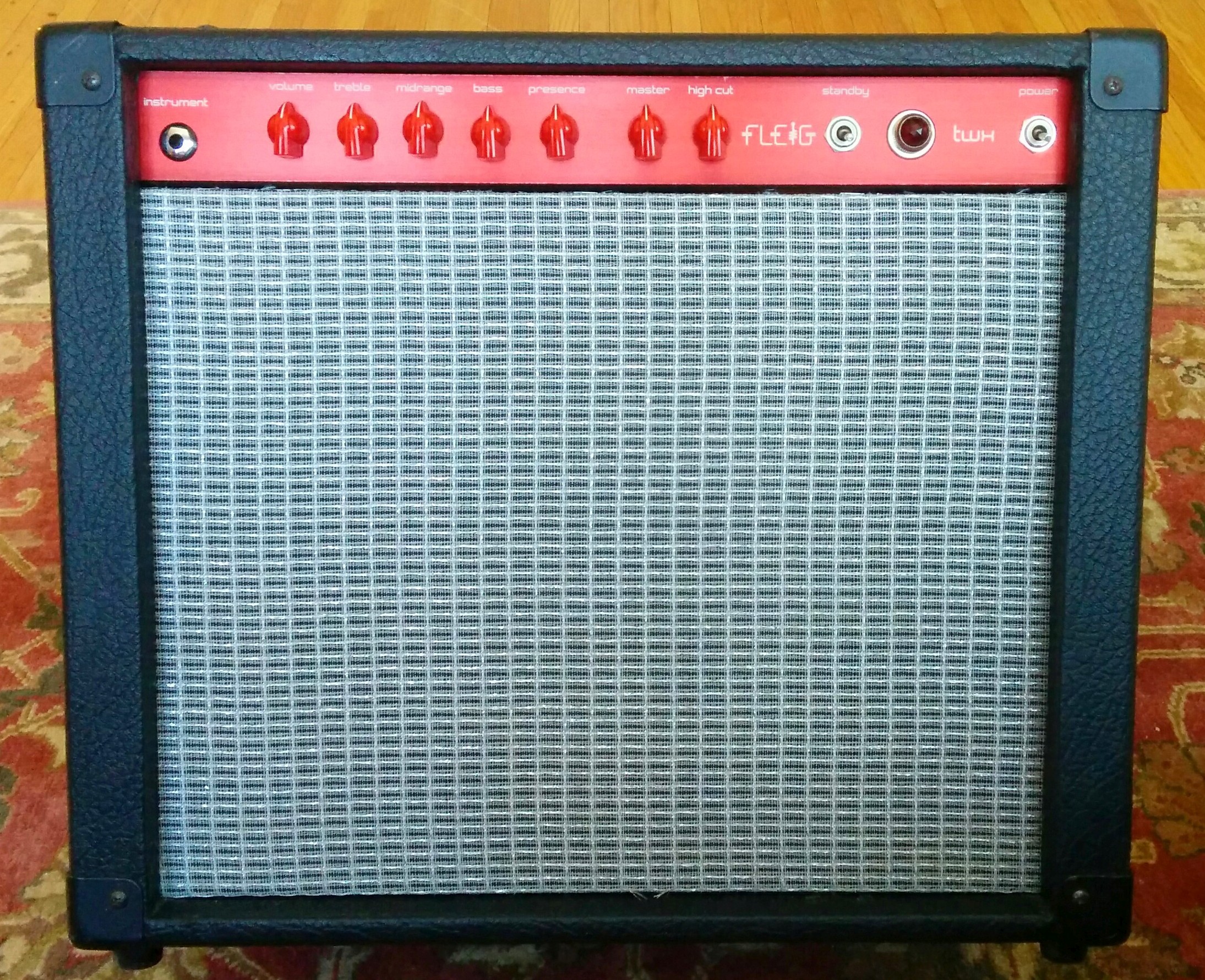
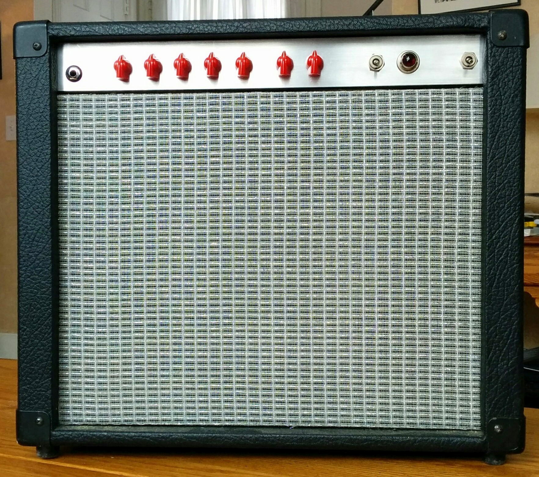
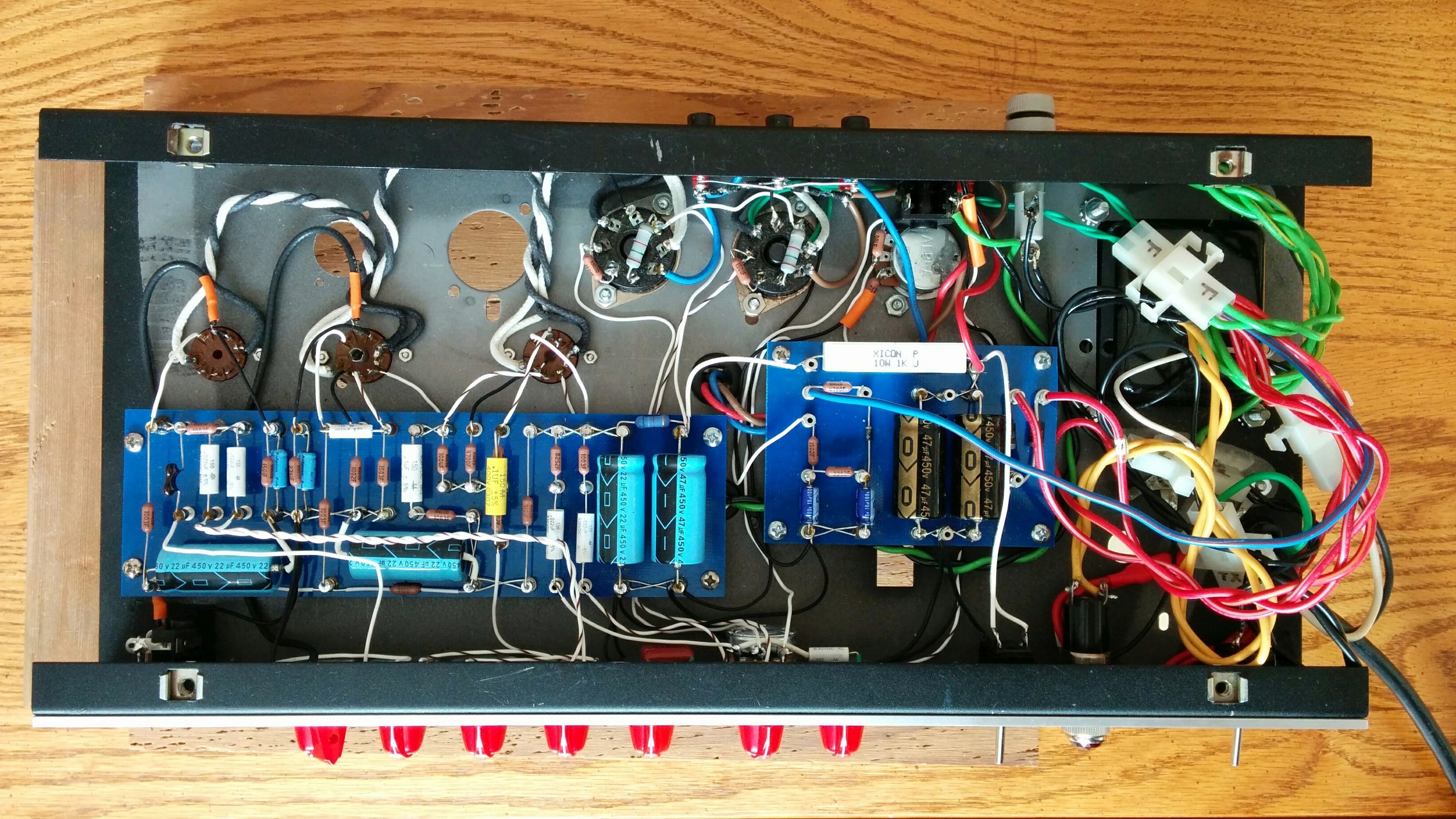
As it appears in its current
incarnation, before the front panel was anodized and labeled. I actually made baffle board and grill cloth (Fender blackface) shortly after my first conversion. |
Research and planning
I have never owned or built a high gain tube guitar amp, but
for quite a while I've have been curious about the mojo
surrounding the work of the late Ken Fisher.
Between the mid 80's and mid 90's, Ken produced about 100 of
his trademark Trainwreck Circuits amplifiers in several
models. Each amplifier is identified by a woman's
name, rather than a serial number. Reputation and
scarcity have taken the resale price of his original works
beyond $10,000 His amplifiers have long attracted the
interest of DIY builders. Starting around 1990, hand-drawn
schematics started appearing on the internet, supposedly
derived from examination of the guts of original
specimens. Several boutique builders have sold their
own versions of Fisher's designs, perhaps much as Jim
Marshall got into business making copies of Leo Fender's
1959 Bassman. I won't comment on the ethics or
politics of stealing/copying/borrowing in the guitar amp
business, but it's a sure thing that it happens a lot, for
better and for worse.The special character of the Trainwreck is that the player can take it from sparkly clean to ripping distortion using only the guitar volume pot for basic control.
Fisher's work has spawned a kind of religion, where disciples have documented every aspect of the design and construction of his holy artifacts. In the fundamentalist branch of this religion, it is seen as desirable and necessary to the Trainwreck sound to use the same layout, electronic components, chassis, and cabinet materials used in Fisher's originals. Other adherents believe that Ken's genius lies more in his deep understanding of how to make great guitar amps from standard parts, and that his legacy is better served by developing one's own understanding, rather than by slavishly cloning his artifacts.
I'm not religious about amp building, but I think more hope for enlightenment lies in the second direction. The ampgarage.com forum seemed to be the spiritual center for the study and discussion of all things Trainwreck, so it was there I found the scriptures on how to build one's own holy amplifier. You have to register with the forum to view attachments to posts. I could easily have built mine using the traditional layout, but I wouldn't have learned very much. Since I have built all of my projects from my own layout, I chose to build the Express with my own board layout as well. That way I'll find out if my methods give quiet and stable results for higher gain circuits.
Fisher was reportedly quite forthcoming about his design philosophy, and shared many of his insights in writings, and conversations with other builders. I haven't studied these much, but I think I understand enough about his general practice to feel confident proceeding as I did.
Original Trainwrecks do not include a master volume. To enjoy a Trainwreck at a volume that won't result in hearing and/or structural damage, the standard solution is to use an output attenuator. Fisher designed a resistive attenuator that many have found quite satisfactory. Many DIY builders have incorporated master volume controls. The Lar-Mar post-phase-inverter master volume circuit (PPIMV) , named after its creators, seems pretty popular. A high-cut control attached to the master volume is another popular addition for taming the harsh high frequencies that can come through when playing distorted, especially with the master volume turned down. My build includes both the Lar-Mar PPIMV and the high cut control.
To minimize the construction costs of my first Trainwreck, I built my Express using an existing combo cabinet, speaker, chassis, and transformer set. My belief is that the critical factors in the success of a design rely much more on the first-order properties of the circuit, i.e. its gain structure, topology, operating points, and good construction practice than on particular brands and models of electronic components. That said, I do believe that transformers matter a lot, and I was prepared to accept that my use of semi-random power and output transformers might not result in the sonic nirvana promised by using the blessed components.
I borrowed a few layout details from Rick Norman, aka Dr. Vintage. There is a Trainwreck Express build page on his website that does not appear to be accessible through his index. The page says not to link to it without written permission, so I'm honoring that request. It is easy enough to find with a search engine. One of his changes that I used moves the unused triode section to V1, rather than V2, to allow tube substitution to adjust the gain structure in a more useful way. My particular interest was using the second triode section in V1 to parallel the first gain stage, as in some Matchless amps. For now I'm leaving it unused to see how the standard arrangement sounds.
Because Ken Fisher's amplifiers have been intensively documented, studied, discussed, and DIY built by many others, I am not representing that my documentation should be worthy of inclusion in the holy scripture of Trainwreck. My original contribution is a new circuit board layout that worked well for me, and that may be of value to other DIY builders.
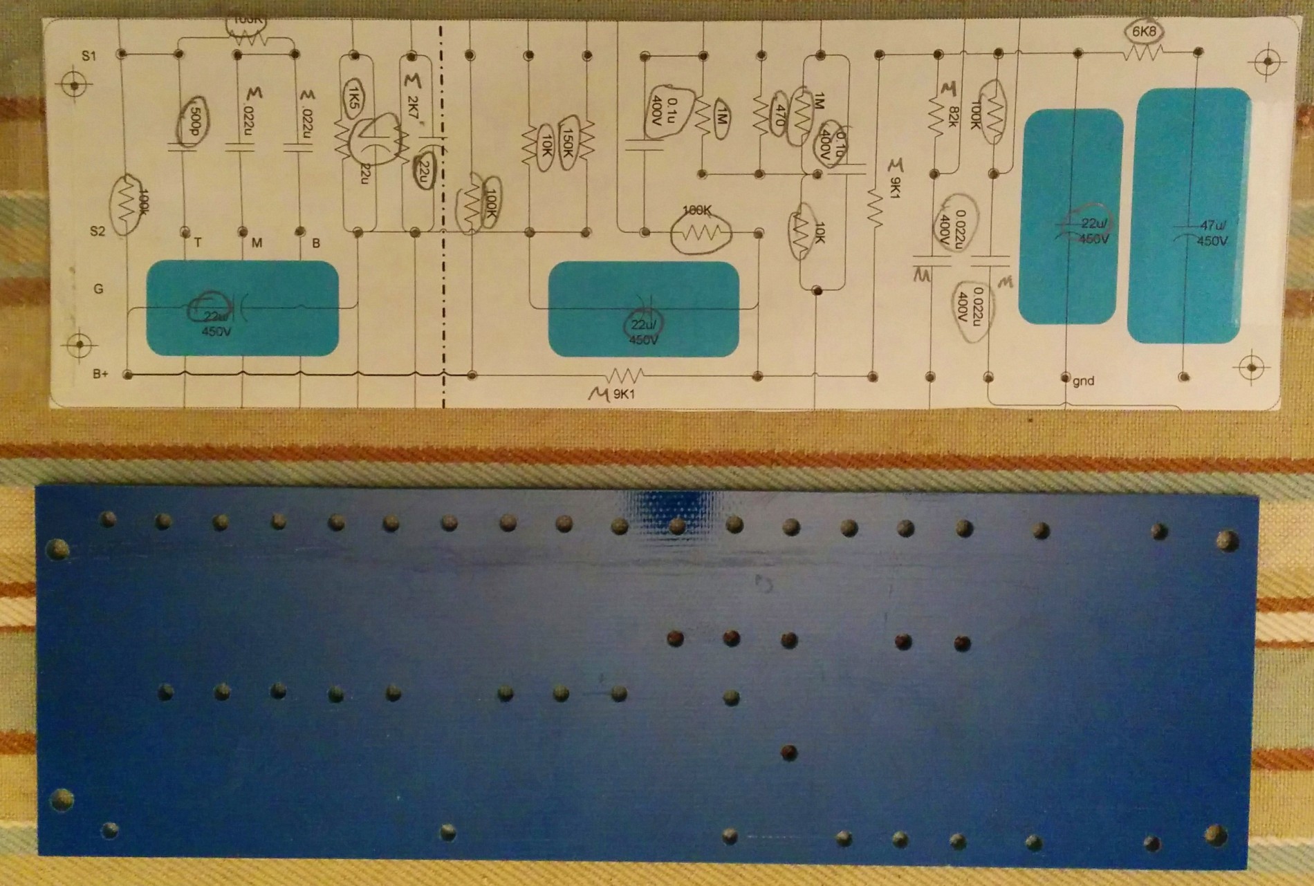
Circuit board layout
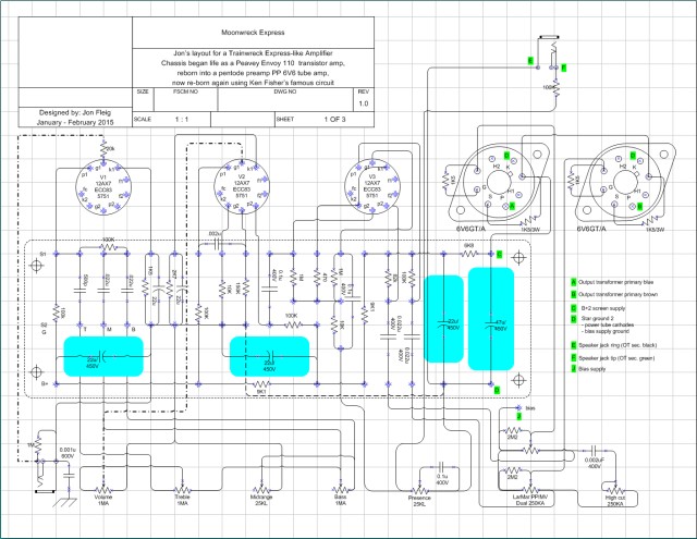 |
My first exercise for this project
was figuring out if I could lay out the main circuit
board on a leftover 8" x 3.125" piece of 1/8" thick
G10-FR4 board. I succeeded using my
traditional layout rules, which more or less follows
Doug Hoffman's
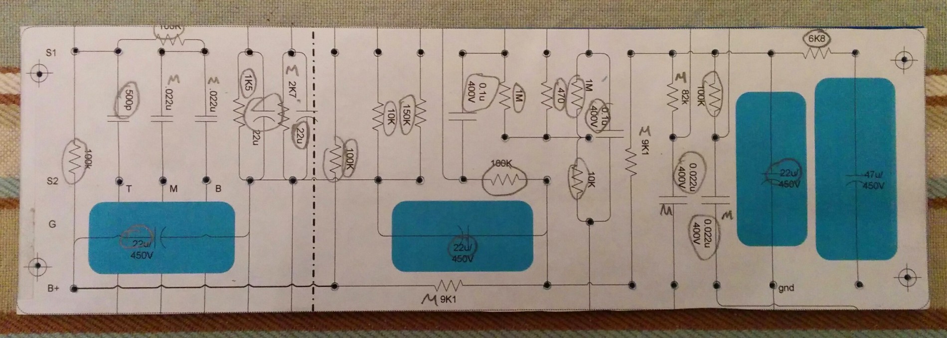
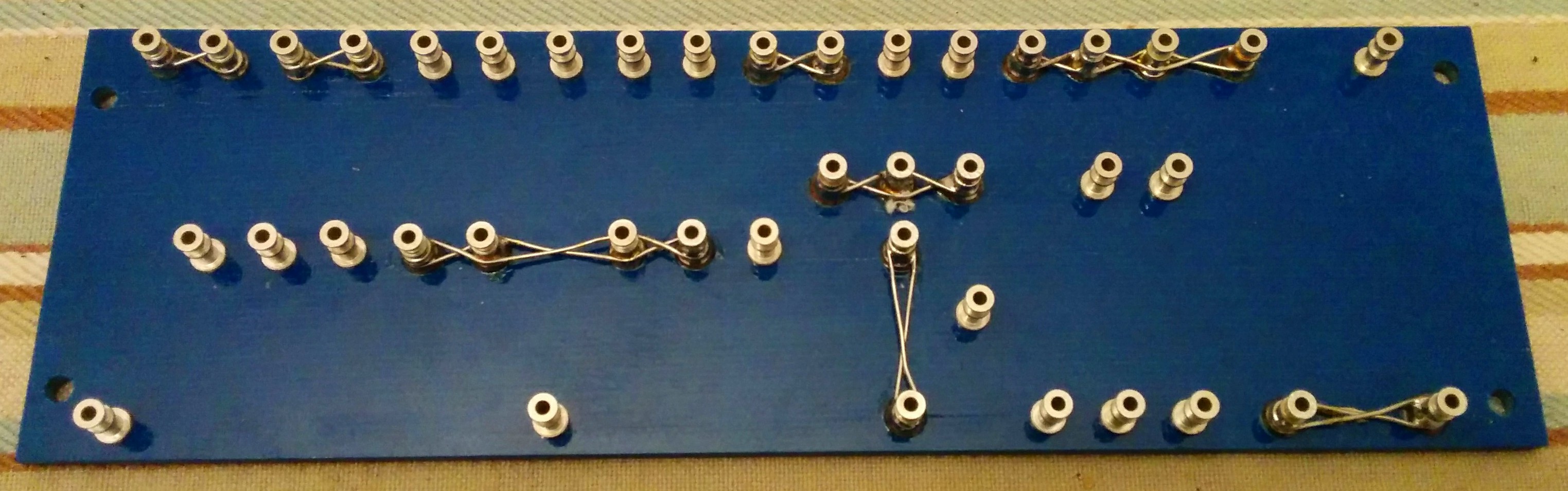
style. After that, I laid out the power supply (HV rectifier, reservoir caps, and bias supply) on another 4" long leftover scrap of board. My preferred style places filter capacitors on the main circuit board close to the section each serves. The negative lead goes right to the cathode grounds. There is only one jumper under the board, connecting the preamp stage ground buss to the phase inverter ground. There is only one connection from the chassis to signal ground: the HV center tap, filament center tap, and reservoir cap ground are attached to ring terminals and screwed to the chassis near the power transformer. I do not tie my signal ground to the potentiometer bodies, nor do I use a separate off-board ground buss wire. Ground connections from pots and jacks are made by directly wiring the control's terminal to the cathode ground point of the appropriate stage on the main circuit board. To keep radio frequency interference from coming in at the input jack, a 0.001 uF ceramic capacitor connects the ground of the isolated input jack (CliffUK) to the chassis. I also found it necessary to mount a stopper resistor (20k) on the first gain stage grid pin to kill RF coming in with the guitar signal. I didn't try any other value, so I can't say I know the minimum value needed to perform this function. I've mounted the output tube grid and screen resistors on pins 1 and 6 of the octal sockets. These are unused on 6V6's (and 6L6's). If you want to use my layout with EL34's, these pins connect inside the tube, so you'll have to mount these resistors somewhere else. |
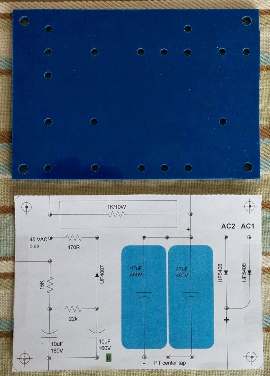
Power supply
 |
The Trainwreck Express wants a stiff
power supply. Fisher used a high current
capacity power transformer, solid state diode
rectifiers, and high reservoir capacitance.
However, he ran the tubes with lower B+ voltages
than Fender or Marshall favored, and biased the
power tubes for relatively low to moderate plate
current. Canonically, the Express uses EL34
output tubes, but Fisher designed it to be able to
use 6V6 output tubes just by re-biasing. My PT
and OT were designed to drive a pair of 6V6's.
With various rectifier options and high and low
voltage taps, my PT can supply anything from Fender
Tweed to Blackface sorts of voltages and
currents. The "official" Express PT has a
300-0-300 HV winding, and no separate bias
tap. Its standard B+ at the reservoir cap is
about 400 VDC at 300 mA. My existing
power transformer from Ted Weber has
340-270-0-270-340 windings with a 45V bias
tap. With full wave diode rectifier, the
270-0-270 winding predicted a B+ of 375 VDC at 150
mA, which is just fine for 6V6's. My
transformer's 340-0-340 taps are useful for amps
like the Fender Deluxe Reverb that use tube
rectifiers and run the output tubes at high
voltages, but this is way too high for
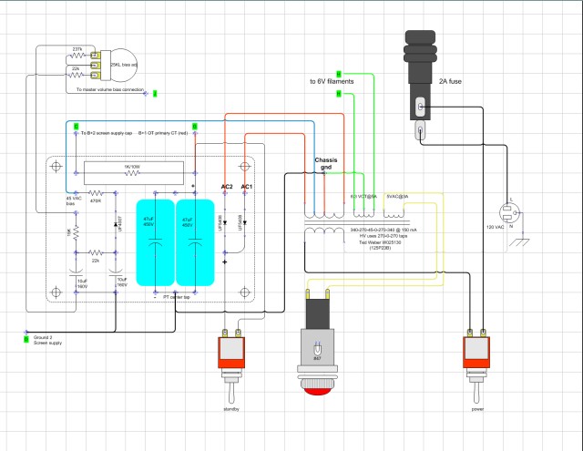
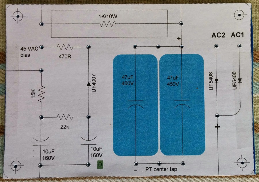
Trainwreck-like applications. The rectifier diodes are usually specified as 2 x 1N4007 (1000 PIV / 1A) in series for each leg. I used a single UF5408 (1000 PIV / 3A) for each leg of the full wave rectifier. This may not have been a good choice. A few days ago, one of my UF5408 diodes shorted out, blowing the mains fuse. I replaced both diodes. If it happens again, I will use 2 x UF4007's in series, as this doubles the peak reverse voltage capacity. I used 2 x 47 uF @ 450V filter capacitors in parallel for the main reservoir filter capacitor. I can use caps rated for 450 VDC here because I am using the lower voltage HV taps on the power transformer (540 VAC). The standard dropping resistor between the reservoir capacitor and the screen filter capacitor is 1000 ohms @ 25 watts. Since this resistor only carries the current for the output tube screens and preamp plates, the total current passing through this resistor is 6 mA at idle, and maybe 12 mA at full power. This gives a power dissipation in the resistor of I * I * R = 0.012A * 0.012A * 1000 Ohms = 0.15W. A 25 Watt resistor here seems to be pure overkill. I substituted a 1000 ohm 10W cement resistor. Update: Why a 25W screen supply resistor is not overkillMany other builders beside me came to the conclusion that a 25W resistor was overkill when the idle dissipation at this node is less than one watt. However, when an EL34 is driven near or above its zero bias point, screen current increases very rapidly. This probably applies to beam power tubes such as the 6V6 as well. This issue is discussed periodically on Ampgarage and EL34World, and the arguments for why Fisher used a 25W resistor here seem solid enough to recommend sticking with that value.Since I'm only going to use 6V6's, and will probably crank it up rarely, I feel OK leaving the 10W resistor in there. However, I will probably use a 25W resistor here in future builds. The standard dropping resistor between the screen filter cap and the phase inverter filter is 18.2K. Since my B+ is ~370V rather than ~400V, I lowered this value to 6.8K to bring the remainder of the preamp voltages up to the normal Express values. The bias supply differs slightly from the standard version. Because my PT has a 45 VAC bias tap, I don't have to use a large resistor off the HV winding to obtain the bias voltage. I looked at the AA763 Fender Deluxe Reverb to see what series resistance was used between the bias tap and the rectifier diode: 470 ohms. I used a 25K linear pot for the bias adjustment, and with a 15K fixed resistor above the pot, and a 22K resistor below the pot to give me a bias range of about -16 to -35 VDC. A 237K resistor connects the bias pot wiper to the bias voltage, to prevent a no-bias condition if the pot fails. I used the otherwise unneeded 5V rectifier winding to power the pilot lamp. |
Chassis layout
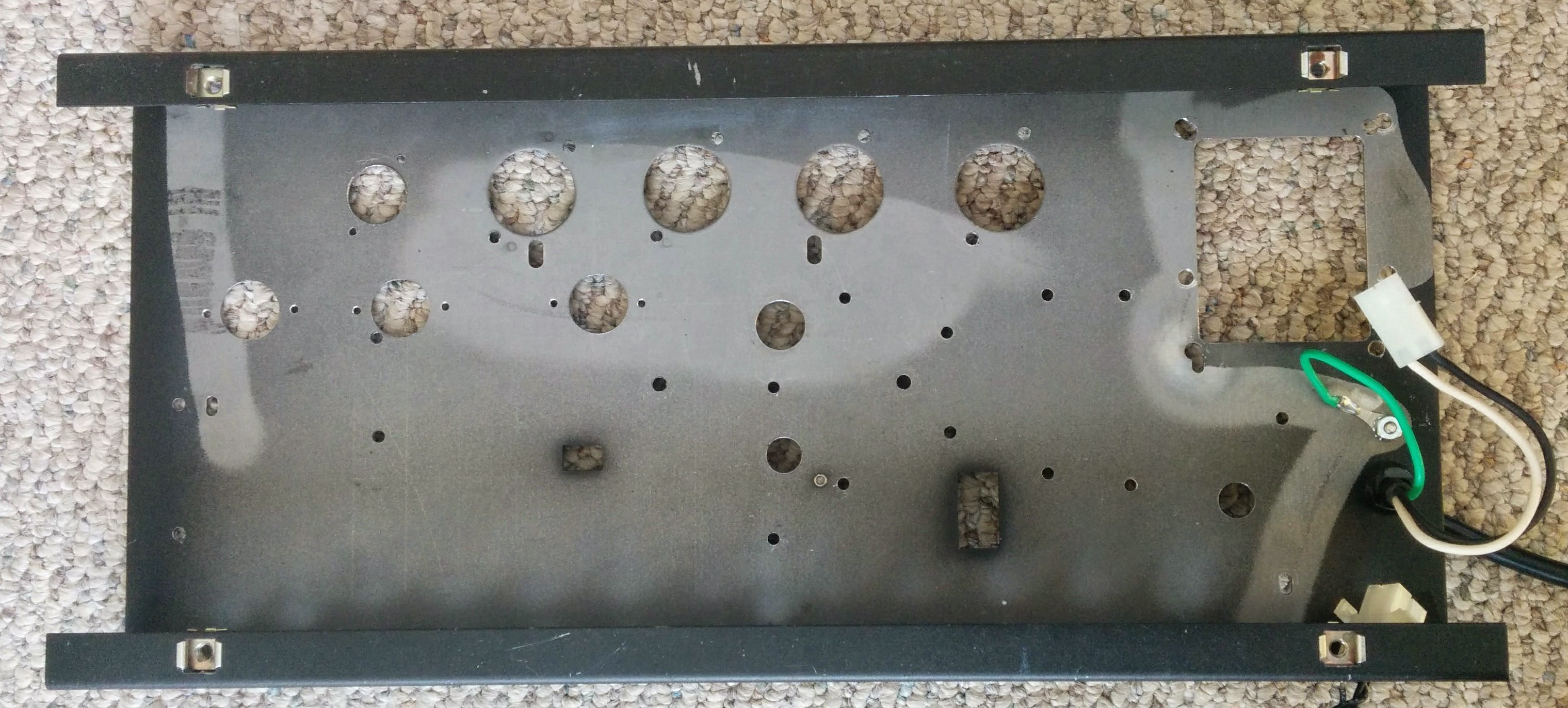 |
The chassis is recycled from two
previous builds: the way it left the factory, and
the first conversion from solid state to vacuum
tube. Thus, the chassis and control layout had
to be adapted to the existing holes. The
removal of the octal rectifier and phase inverter
tubes left two empty octal socket holes. To
keep the wires from the board to preamp tube sockets
short, I drilled new holes for 3 miniature tube
sockets, leaving the original preamp tube socket
hole empty. My friend Arpad made covers for
the unused octal socket holes from scrap
aluminum. I installed the bias pot in the
cover for the former rectifier tube socket. I
may eventually make beauty covers for the surplus
miniature tube socket hole and rear panel control
holes. Neither the power transformer nor the output transformer are mounted in the traditional locations for original Trainwrecks. I simply retained the power and output transformer locations from my previous build in this chassis, because I already knew that the OT did not pick up hum in its current location and orientation. Since this is a steel chassis that couples magnetic flux from transformers, and not the aluminum preferred by Fisher, I saw no reason to risk moving it to obtain the traditional layout. |
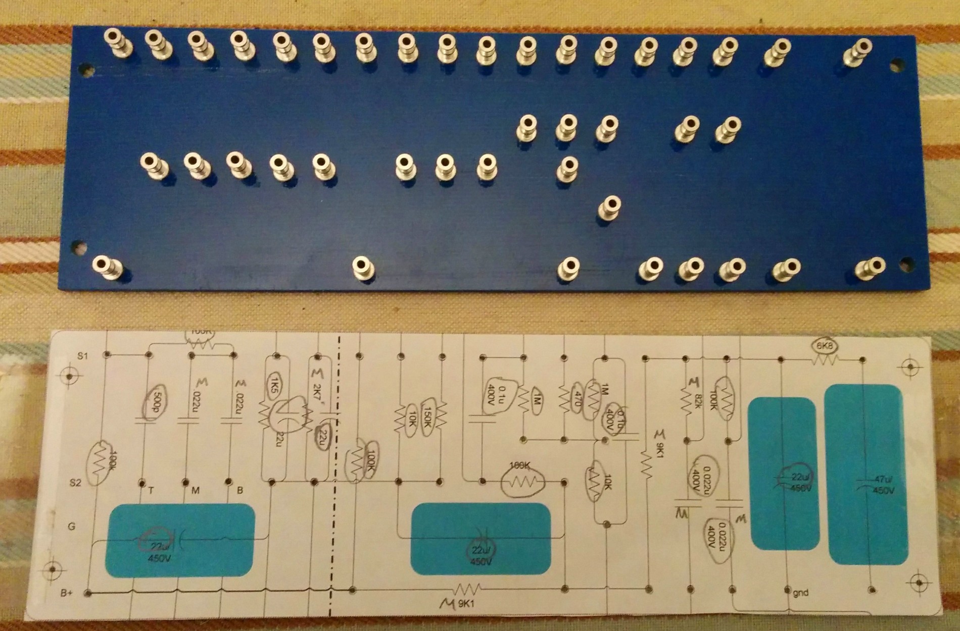
Fabricating the main and power supply circuit boards
 |
The full size template
for each board is printed and taped to the
board. I use a spring loaded center punch to
mark the location of each hole to be drilled.
My basic vertical and horizontal grid is 0.375"
(3/8"). I alter the grid where necessary to
accommodate larger components, like filter caps. |
 |
 |
The main turret board is
8" x 2.5" constructed on 0.125" G10-FR4 glass-epoxy
(aka Garolite) from McMaster-Carr.
The power supply board is 4" x 2.75". The drill size is #33 (0.113"), which is just 0.001" larger than the turret body for a very snug fit. It is critical to use the correct size drill for the turrets |
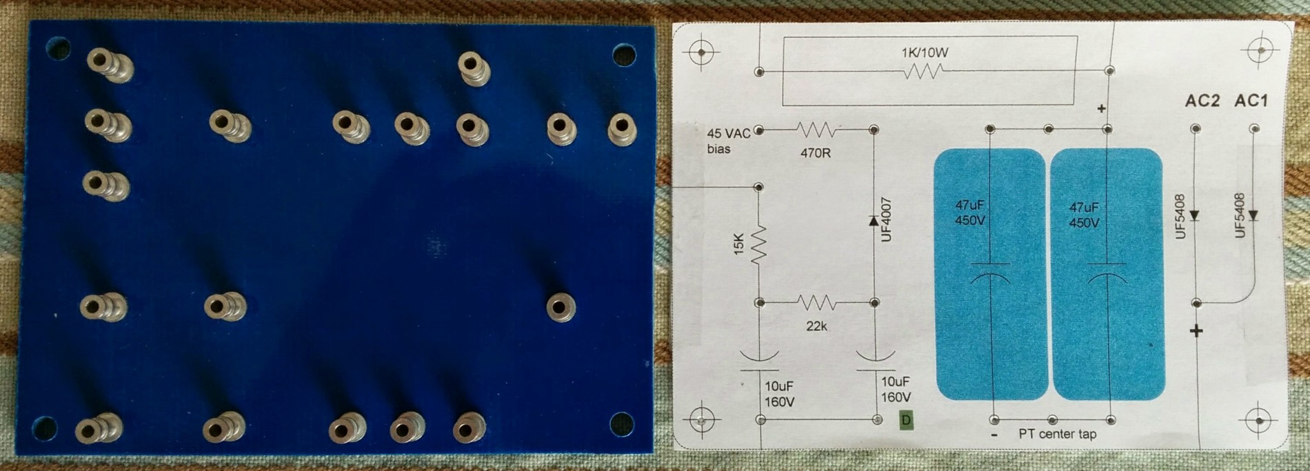
 |
 |
The Keystone turret
lugs are Mouser
Electronics part 534-1509-4. They are
now very expensive, ($0.25/per), even when ordered
in 1000 quantity. I set the turrets on my drill press (not plugged in) using the Keystone staking tool 534-TL-8, also available from Mouser. The pointed end of the Keystone tool has a complex profile that flares every turret perfectly. It was worth an $18 tool to not ruin any more turrets. |
 |
 |
The appropriate turrets are laced together with #22 soft tinned buss wire, using Doug Hoffman's technique. | 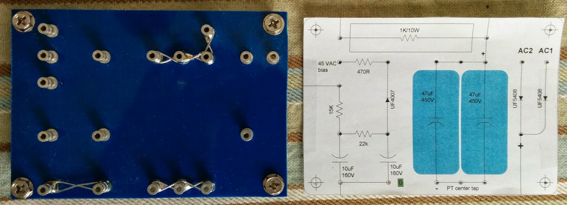 |
Front panel controls
The original front panel of the Peavey had plenty of holes for the controls. I added a few more holes and resized some others during the course of my original tube conversion project. Needless to say, it was in a pretty ugly state at the start of this project.
 I had several blank 19" x
1.75" x 0.125" aluminum panels left over from my 1U rack
preamp projects. It turns out that the Peavey's front
panel was 1.75" high, so it was natural to hide the ugly
chassis panel with one of the aluminum blanks. Arpad
trimmed the rack ears off a panel blank, and drilled the
control holes on his Bridgeport mill. The front panel
cover brought two complications: the added thickness
of the aluminum panel over the steel chassis only left a few
threads exposed on the potentiometer bushings.
Fortunately, that was enough for the retaining nuts to
hold. The second problem was that the added thickness
pushed the chassis back from the mounting screw locations in
the combo cabinet. I could have trimmed an additional
3/4" from each end of the aluminum panel, so the panel would
not change the location of the chassis in the cabinet, but I
really liked the look of the full width cover. I
borrowed a 1/8" end mill from Arpad, chucked it in my hand
drill, and elongated the holes in the cabinet by 3 mm.
The beauty washers for the chassis mounting screws were
large enough to cover the elongated holes, so my quick hack
doesn't show.
I had several blank 19" x
1.75" x 0.125" aluminum panels left over from my 1U rack
preamp projects. It turns out that the Peavey's front
panel was 1.75" high, so it was natural to hide the ugly
chassis panel with one of the aluminum blanks. Arpad
trimmed the rack ears off a panel blank, and drilled the
control holes on his Bridgeport mill. The front panel
cover brought two complications: the added thickness
of the aluminum panel over the steel chassis only left a few
threads exposed on the potentiometer bushings.
Fortunately, that was enough for the retaining nuts to
hold. The second problem was that the added thickness
pushed the chassis back from the mounting screw locations in
the combo cabinet. I could have trimmed an additional
3/4" from each end of the aluminum panel, so the panel would
not change the location of the chassis in the cabinet, but I
really liked the look of the full width cover. I
borrowed a 1/8" end mill from Arpad, chucked it in my hand
drill, and elongated the holes in the cabinet by 3 mm.
The beauty washers for the chassis mounting screws were
large enough to cover the elongated holes, so my quick hack
doesn't show.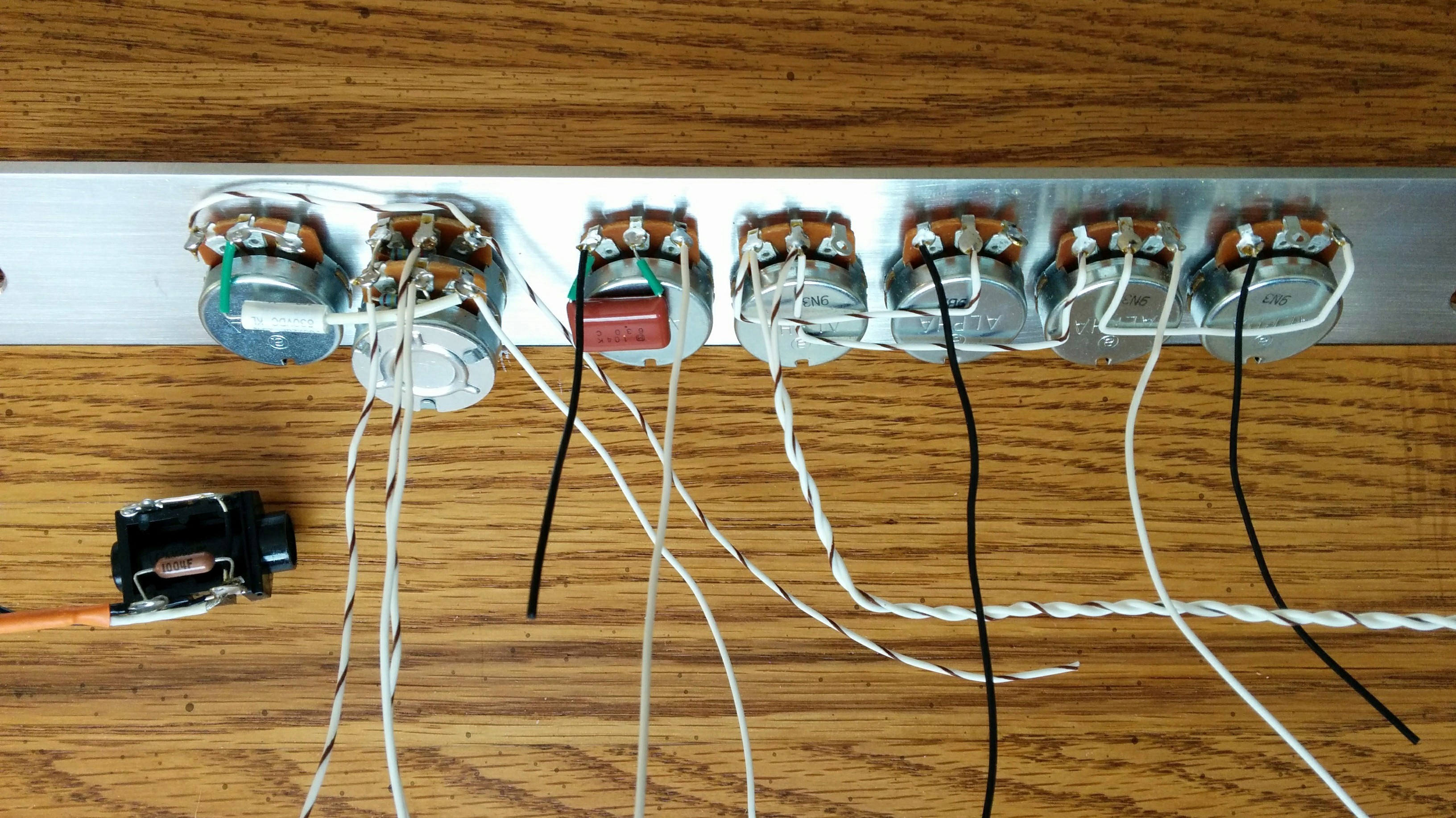
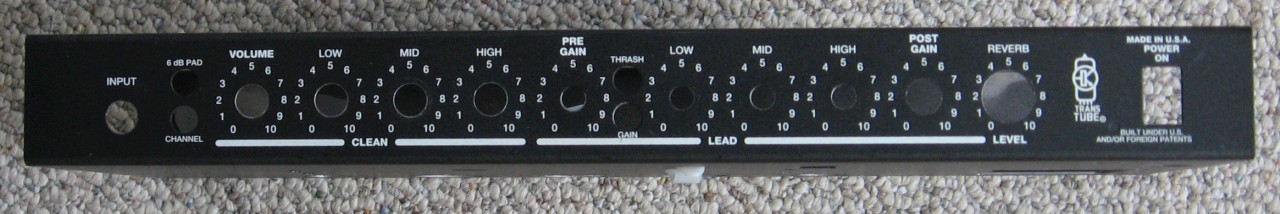
The aluminum front panel cover made a convenient way to wire the front panel controls, mounted in their correct positions, without having to do this inside the chassis. That would have been a nightmare, because the U-fold in the chassis makes the potentiometer terminals nearly inaccessible. From left to right, the controls are high cut, master volume, presence, bass, middle, treble, and volume.
Jon, another co-worker of mine, arranged to get the front panel anodized and laser engraved. I was going to make another attempt to etch it myself using toner transfer and copper sulfate solution, but I was happy to take the easy way out. The standard non-hack way to obtain an attractive front panel would have been to order a laser-engraved or silk-screened beauty panel made from thin aluminum, but I'm happy with the results obtained by using materials I had on hand, and the generous contribution of volunteer labor from of a couple friends.
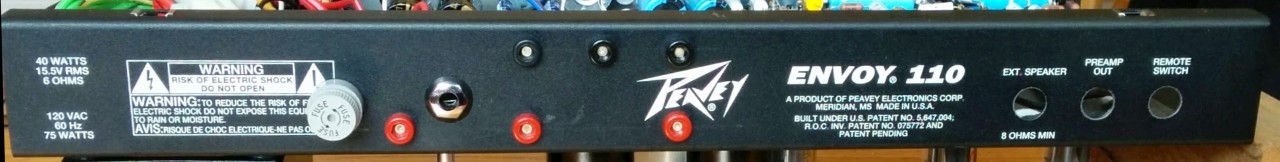
Rear panel controls
The rear panel of the Peavey had some extra holes where I didn't need them. I drilled new holes for the fuse holder, speaker jack, and 6 bias voltage monitoring probe jacks.My output transformer only has 8 ohm output, so there is no impedance selector. I'll eventually make a beauty cover for the rear panel. For now, it's gonna keep showing its Peavey tattoos.
The red probe jacks are, left to right, B+ at output transformer center tap, and plate voltage for each 6V6 output tube. The upper jacks are 6V6 #2 cathode, cathode ground, and 6V6 #1 cathode. I can thus set output tube bias using either the cathodes or the plates.
Assembly and first power up test.
Things went together pretty well. The only part that
was difficult to wire is all the stuff by the rear
panel. Since this chassis is about an inch less deep
than the standard Trainwreck chassis, there is not much
space between the output tube sockets and the rear
panel. It also has less vertical space than a
typical tube amp chassis. Since I included 6 voltage
probe jacks for output tube anodes, cathodes, cathode
ground, and OT center cap, the area by the output tube
sockets and output jack is pretty crowded. I'm glad I
made an accurate scaled chassis layout in Visio. It
would have been less hairy if I were starting with a new
blank chassis, but my adaptation of the recycled chassis was
satisfactory.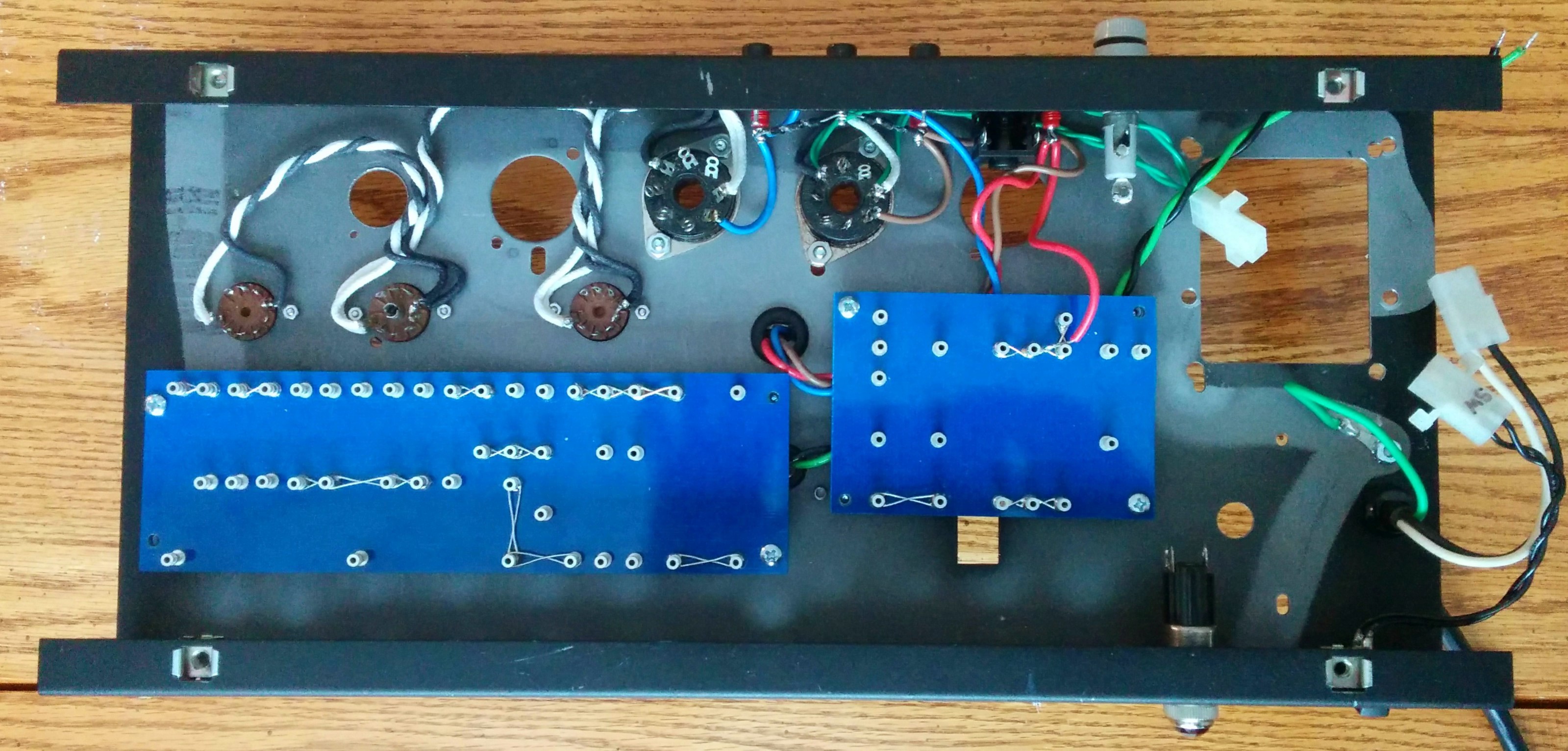 |
 |
 |
 |
| Filament and power tube wiring
complete. Checking circuit board fit. |
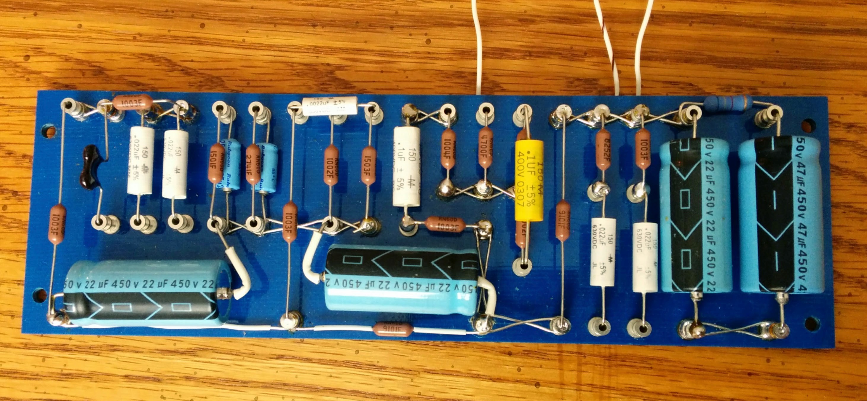
Components inserted into main circuit
board. Many connections are soldered after the
board is mounted in the chassis. |
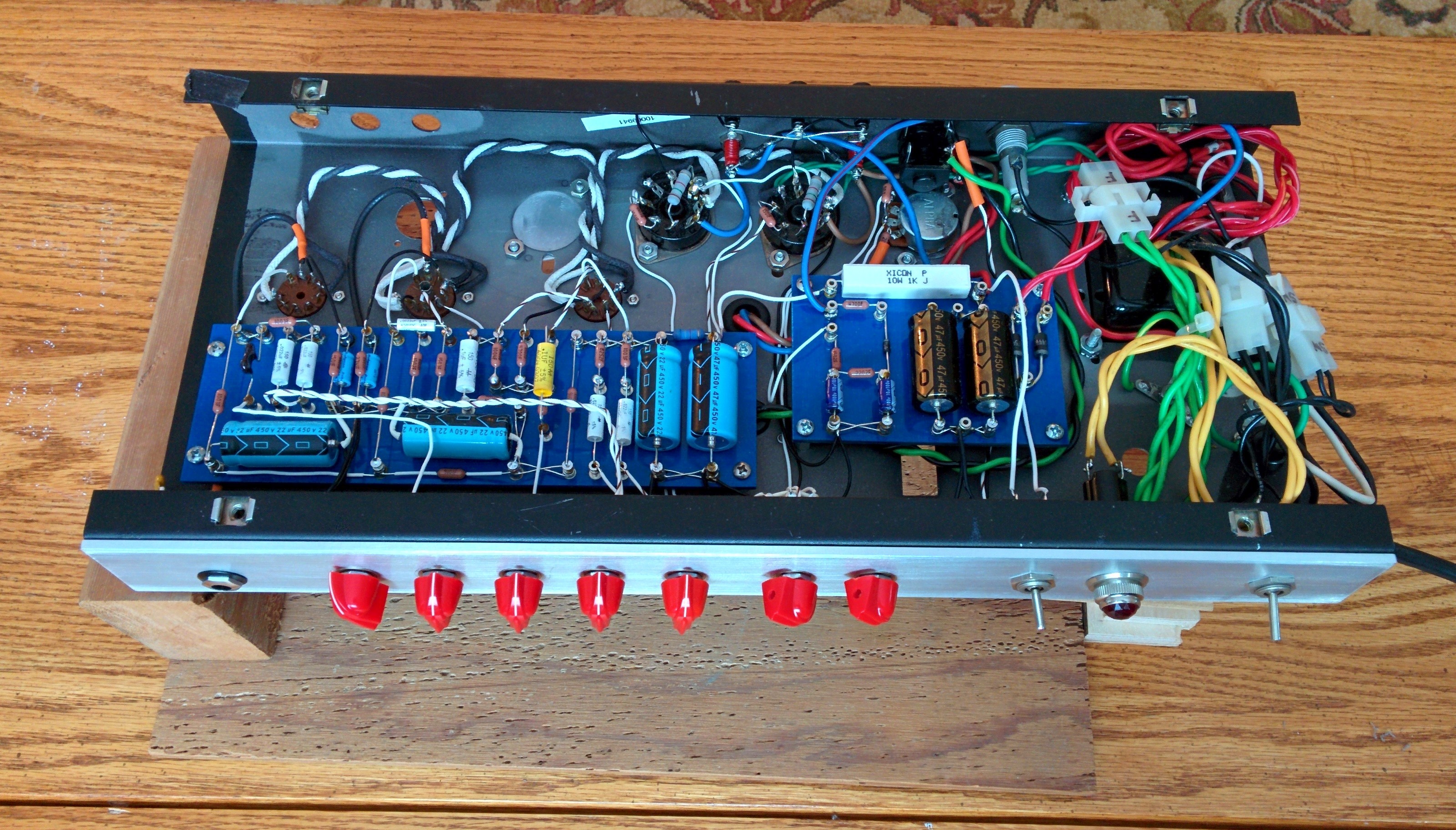
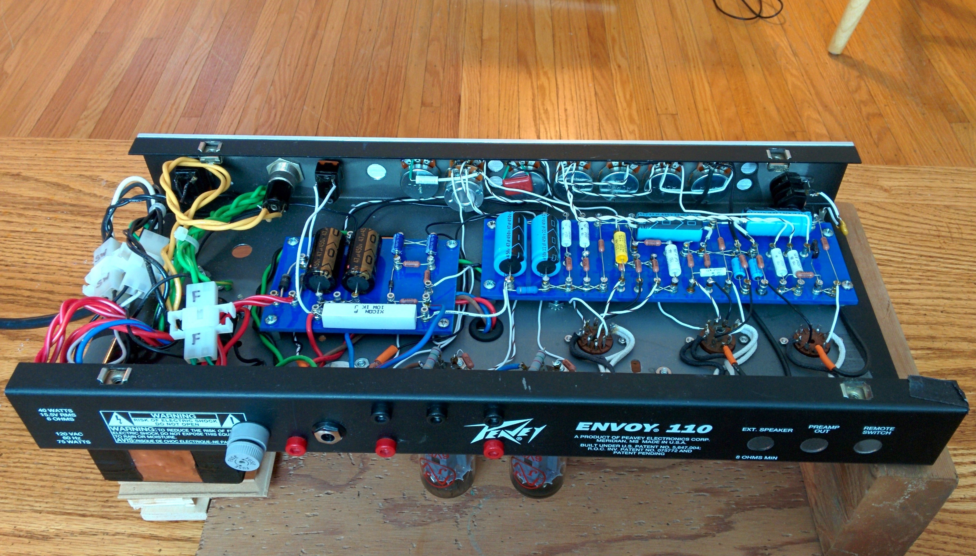
Front view of assembled chassis on my
test stand |
Rear view of assembled chassis on my
test stand. |
For my own "experimental" builds, I don't trim the transformer leads short for maximum neatness, as the transformers may get moved to a different chassis someday. So I braided them and secured them with nylon wire ties.
After wiring everything, I verified that there was high resistance between all power rails and ground, the low resistance between all ground points. Then I began power-up testing with a variable autotransformer (Variac), with the tubes removed. During this process, I discovered two problems: I forgot to ground the positive side of the bias supply to the screen ground, and I forgot the resistor between the bias pot and ground needed to scale its voltage into the proper range. It was late, so I shut down and went to bed. The next morning, I corrected these problems and installed the tubes. I set the bias for maximum negative voltage. With the power and standby switches turned on, a guitar connected to the input, and a speaker connected to the output, I slowly brought up the voltage on the variac. After about minute with no indications of trouble, I reached a B+ voltage of about 200 VDC, and the filaments were hot enough for cathode emission. Beautiful clean tones emerged from the speaker. It worked on the first try! I continued slowly raising the mains voltage until it reached 120 VAC, and nothing bad happened. I did a quick check of all the B+ node, plate, and cathode voltages: everything looked good.
Setting the bias
I built in probe jacks to measure the voltage drop across 1 ohm resistors between the power tube cathodes and ground, but I neglected to order said resistors with the other parts for this build. No big deal. I just wired a jumper between the cathode probe jacks and cathode ground. I'll replace the jumpers with 1 ohm resistors after my next parts order. Another good way to measure idle plate current is to measure the DC resistance between the output transformer primary center tap and each plate lead. Of course one measures this resistance with the power OFF. For my OT, a Weber W041318, that was about 140 ohms per leg. Plate current for each tube can then be calculated from the voltage drop between the OT center tap and plate lead using Ohm's law. So if I wanted to bias each 6V6 for 25 mA plate current, I'd want to see V = I * R = 0.025A x 140 ohms = -3.5 VDC between the OT CT and each plate lead. With 370 VDC on the plate, 25 mA gives 9.25 W idle plate dissipation. The JJ 6V6-S's I'm using are specified for 14W max dissipation, so my idle dissipation is about 67% of max. This might be a bit hot for an Express with heavily overdriven output tubes, but I don't expect to be there much. At some point, I'll hook up a dummy load and make sure I'm not red-plating in a darkened room when I've got it cranked. In any case, when I adjusted the bias pot to give me a 3.5 VDC drop from CT to plate, the bias voltage was -31 VDC at a plate voltage of 370 VDC. This agrees well with the nominal curves shown on the JJ's plate characteristics chart for this tube. When using this OT voltage drop method to measure plate current, it is important to let the tubes and the OT to warm up, as the OT's resistance will drop as its temperature rises. At some point, I intend to cross-check the results among the three "good" bias measurement methods (direct plate shunt current measurement being the third method).
Sound check
With the bias set, it was time to check the sound. The amp sounded pretty awesome, just like the sound and video clips posted on YouTube, et. al. Everything from shimmery clean to Van Halen grind is on tap, just by turning the guitar's volume pot. The speaker in the combo cabinet is a Weber Signature 10S Alnico, rated for 15W. I think it sounds very nice in this amp, smooth with good balance everywhere. I'm slightly afraid that this amp has the power to destroy it if I get too enthusiastic. I also tried my EVM 12L (150W) in an external cabinet, and that thing was monstrous, tight as a drum with lows the Weber couldn't touch. That's not a knock on the Weber, as those speakers are very different animals. I also tried a budget Weber Signature 10 ceramic. That one was all midrange, and not enough treble for the way I play.It was a radio too, for a little while
I had an FM radio station coming out of the speakers intermittently, so RF was getting in. During my initial testing, I had no RF cap between the input jack ring terminal and chassis ground, and no grid stopper resistor on the input. I add the RF cap, and that took care of most of it, but some was apparently coming in on the instrument signal lead. I added a 20K grid stopper on the input triode's grid pin, and the radio was gone. I didn't notice any damage to the amp's "touch sensitivity", or any additional treble loss with the guitar's volume knob turned down.No squeals or oscillation with everything dimed
I think I've got it all wired nice and tight, with no unintended feedback between stages. I'm not quite sure if the negative feedback (NFB) in the presence control is ideal. I used a 100K resistor between the OT secondary and the phase inverter tail, with a 25K presence pot instead of the "correct" 5K pot. Another item for the next parts order. With minimum NFB, the gain is pretty darn high, and I can hear taps on the chassis and at least one preamp tube pretty well. I may have to do something about damping microphonic tendencies in the preamp tubes.I looked for oscillations everywhere with my oscilloscope, and didn't see any. Nor did I hear any weird intermodulation tones while playing the guitar.