|
|
|
Updated: 3/16/2004
T-18 Conversion:
This project was done about 10 years ago and no pictures were taken at the time. The original transmission was a T-4. I used a kit from Novak Adapters with a transmission from a 1978 2WD Ford F250. The original 1982 bell housing had two dimples where I needed to drill for the lower bolt holes. I used a clutch kit for a late 70's CJ-5 with the factory T-18 and 258 6 cylinder. This conversion was also done along with a axle ratio change from 3.31 to 4.56 so the overall change was dramatic!
OME Wrangler spring conversion:
This was a semi home brew project. Some items including the springs
were purchased from a local shop but didn't include any instructions. The
stock 80's front shock mounts were swapped side to side and lengthened
about 1-1/2". They were swapped in order to retain the original mount configuration
if I ever wanted to return to stock length shocks.
The front spring shackle mounts were moved forward about an inch.
This was done by drilling out the rivet that attaches the front cross member
to the frame rails. After market rear CJ hangers and 1-1/2" longer shackles
were used on the front. These along with YJ length shackles on the rear
gave me about 2-1/2" of lift. The front of the Jeep was always lower than
the rear, mainly because of the Warn 8274 winch that weighed in at 140#'s.
When I replaced that winch with a 8000i the front was almost level.
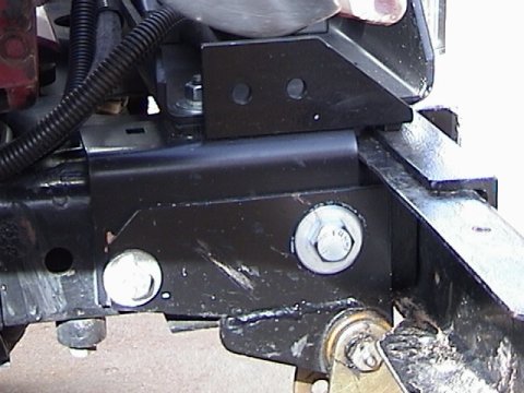
This Picture shows tow hook bracket and front spring hanger to frame tie in. Also notice how the front bumper is notched on the bottom to clear the hanger which was moved forward 1" for the OME YJ spring conversion. This is duplicated on the other side also.
Update 3/2002:
To help with the approach angle, I decided to install OME "fitted
leaves" (add-a-leaf) on the front of the Jeep and replace the 1-1/2" longer
shackles with some 4WDH HD replacements. The fitted leaves made up for
the shorter shackles and the castor wedges I took out at the same time.
I did not notice any difference in the ride when adding the fitted leaves
to the front.
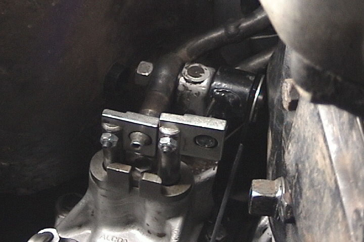
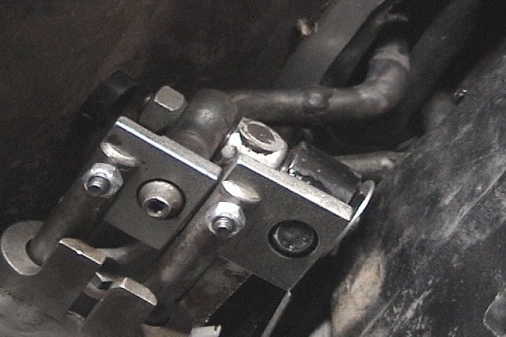
On the original 258 I installed factory a/c brackets and a York compressor. With the 4.0L conversion I kept the original factory Sandan a/c compressor. It has worked great for 2 years now with an occasional squirt of oil into the air inlet. I installed a Sun Performance tank under the rear floor and air outlets front and rear. I also installed a small air regulator to supply the proper pressure for the ARB system.
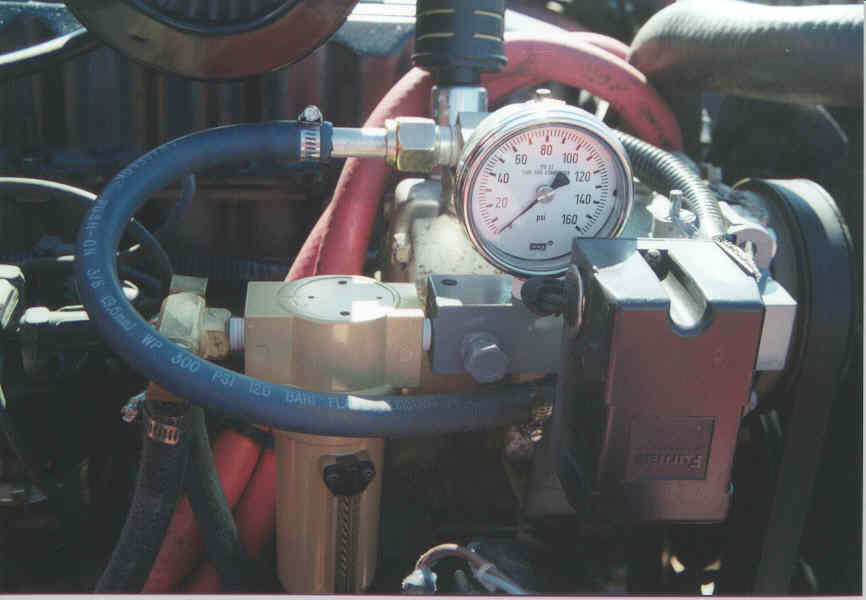
Pressure switch, gauge, inlet filter and outlet filter/coalescer
mounted to manifold.
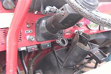
Dana 300 clocking and skid plate modification:
I sent my adapter back to Novak Adapters to have it re-drilled. This puts the case 5 degrees down from true horizontal. I then cut the drop out of the skid plate and gained about 2" of clearance. My 4-Plus twin sticks needed cut, welded and a little heating and bending to fit in the floorboard hole. Modification of the t-case front output retainer in the area of the shifter mount was required to clear the T-18.
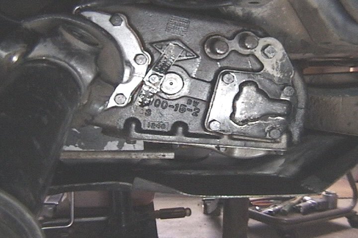
Clocked T-case with modified skid plate
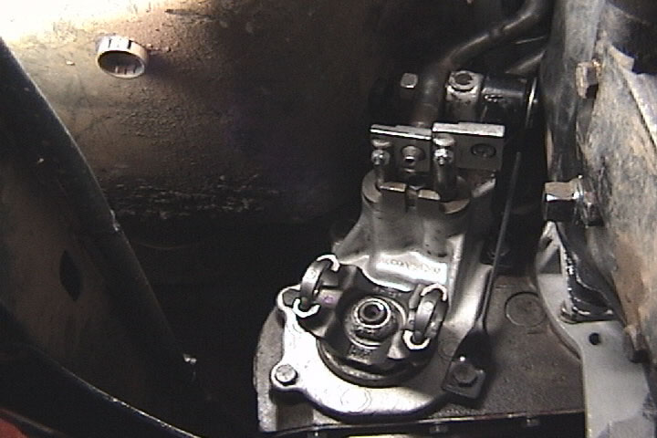
Shifter clearance to T-18, minimal
I made a new pivot bolt and drilled the "R" clip hole closer to
the end. This, with a little chamfer on the end of the bolt allowed 1/8"
clearance to the transmission.
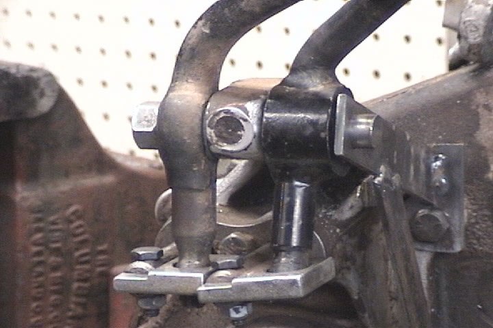
Left picture: Modified shifter bracket, prototype pivot bolt and
new support for inside shift lever.
Right picture: Inside view of finished project. Yes, the tunnel
cover was a stop sign.
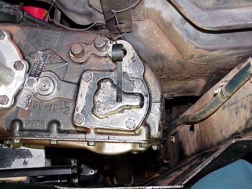
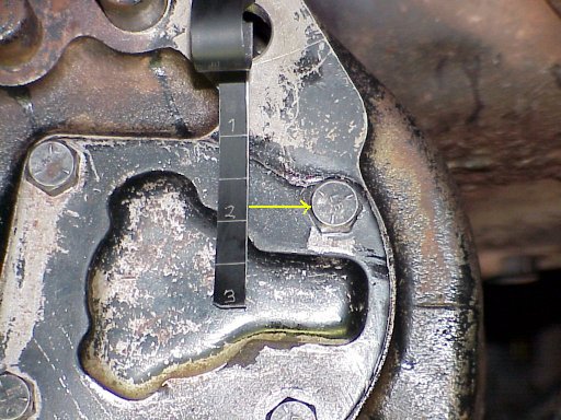
After clocking the t-case, I always wondered what the oil level was when filled with the recomended 4 pints of oil. I made this gauge from a black hose clamp. The oil level is approximatly 1-3/4" down or slightly below center of the bolt hole on the right.
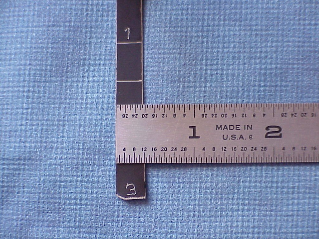
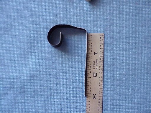
From the bend, the length of the gauge is 3" long with marks at 1", 1-1/2", 2", 2-1/2" and 3". The actual gauge part was cut narrower in order for it to fit more into the bottom of the fill hole.
Sun Performance Products makes this kit but I decided to make my own as detailed below.Manual ARB Actuation Switch
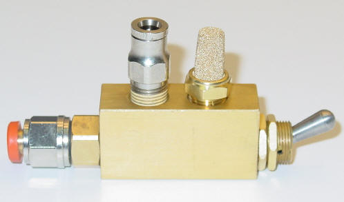
Picture courtesy of Gulf
Coast Rovers
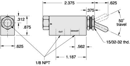
Air valve specifications:
Type: Normally CLOSED, 3 way poppet two position toggle valve.
Medium: Air, Oil , Water
Arc of travel: 50 Degrees
Input Pressure: 300 PSI Max
Air flow: @ 50 psi - 14 SCFM, @100 psi - 25 SCFM
Force for full Toggle Travel: 2 ½ oz. nominal
Temperature range: 32° to 230°F.
Ports: Input 1/8" NPT, Output 1/8" NPT, Exhaust 1/8" NPT
Mounting: 15/32-32 male thread 2 nuts and 2 lock washers
furnished
Manufacture and part number: Clippard,
MJTV-3
The switch was purchased from Sunsource in Salt Lake City UT, (801) 975-9125 for $12.50. The fittings in the above picture are not supplied with the switch. The fittings are called Instant or Push-to-Connect fittings and are nickel plated brass. Mine were purchased from McMaster-Carr.
And yes, these fittings do fit the 5 mm ARB blue air line.
Part number 50405K42 is metric nylon 11 tubing, 3mm id
Part number 51495K183 is a 3/16" tube to 1/8"
NPT male pipe adapter
Part number 51495K233 is a 3/16" tube to 1/8"
NPT male 90* elbow pipe adapter
Part number 51495K112 is a 3/16" tube coupling
(for repair or splicing tube together)
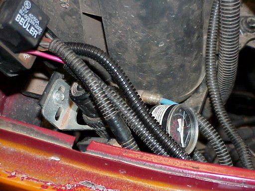
Part number 4450K1 is a 1/8" NPT bronze exhaust filter. It can be
installed at the switch if you don't mind the noise and smell of 90 weight
gear oil. I ran mine out with the other lines and attached it to one of
the battery tray support arms.
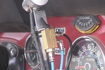
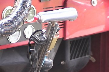
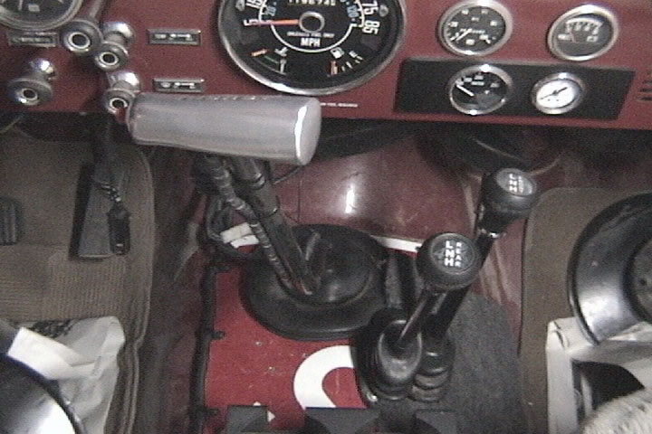
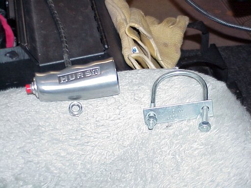
Here is the switch mounted on the T-18 shift lever. The rubber boot was bought from Radio Shack. The right picture also shows the remote switch for the Off Road Engineering electronic idle controller and the red button is for the Hurst Roll Control (line lock).
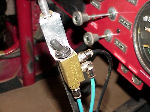
I ran the air lines down the shifter then forward across the floor on top of the carpet. Next I routed them to the small firewall plate below the heater assembly. This plate covers the hole where the factory a/c hoses entered the cab. Using some small grommets in 1/4" holes, I routed the air lines to the engine bay area.
ARB Air Pressure Regulator
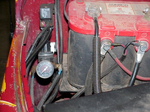
ARB On Light
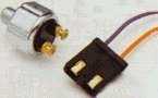 I used
a low pressure brake light switch tee'd into the air line going to
the ARB to activate a dash mounted light. Although this won't tell you
if the locker is engaged, it will tell you that there is air pressure going
to it. This switch is a Painless Wiring item and was purchased from Yearwood
Speed & Custom.
I used
a low pressure brake light switch tee'd into the air line going to
the ARB to activate a dash mounted light. Although this won't tell you
if the locker is engaged, it will tell you that there is air pressure going
to it. This switch is a Painless Wiring item and was purchased from Yearwood
Speed & Custom.
More dash pictures
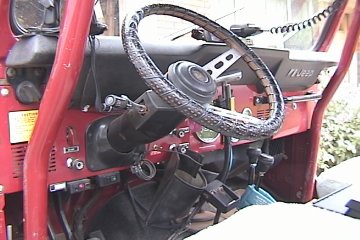
The steering column is from a 1990 XJ. The switch above the light
switch is for the Mico electric brake lock. Below the light switch, on
the dash lower lip, left to right are: MPI check engine light, Off
Road Engineering electronic idle control, and the OBA main power switch.
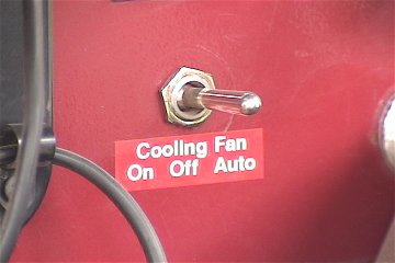
To the right of the column where the original wiper switch was, is the
control switch for the electric cooling fan. This switch is wired for Off,
Manual, and Automatic.
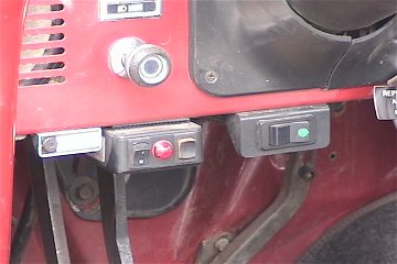
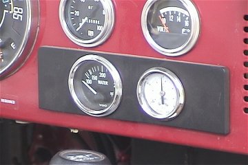
More pictures of the left dash switches. The aftermarket electrical temp gauge and the OBA air gauge are mounted on a 1/4" piece of plexiglass painted black. This is retained in the original radio opening by the gauge brackets.
 The electric cooling fan switch is a DPDT toggle. It's mounted in
the original wiper switch hole now that I use the column mounted wiper
switch. I used a Derale #16759 fan controller that has provisions for A/C
compressor input which is what I used for the manual activation.
The electric cooling fan switch is a DPDT toggle. It's mounted in
the original wiper switch hole now that I use the column mounted wiper
switch. I used a Derale #16759 fan controller that has provisions for A/C
compressor input which is what I used for the manual activation.
4.0L Engine Conversion
Completed Project showing the Rock-It air tube and filter
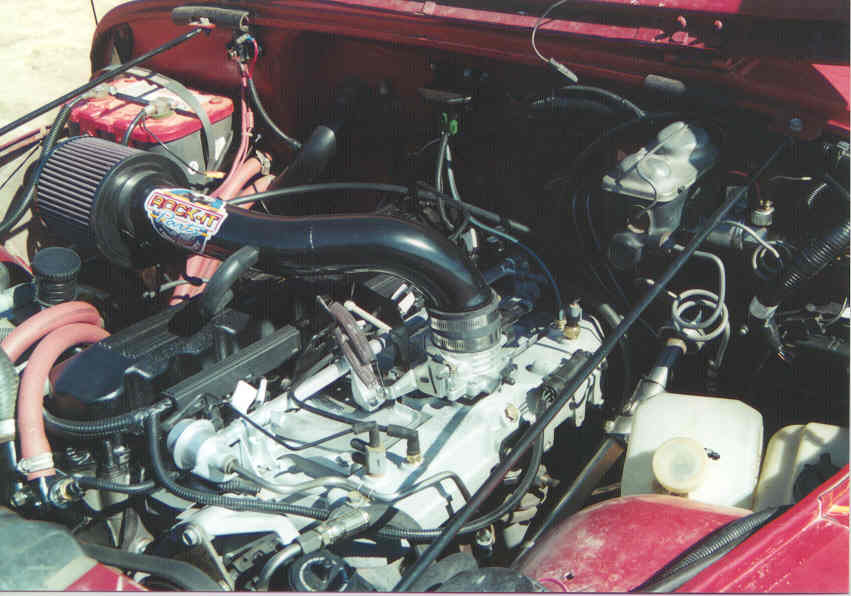
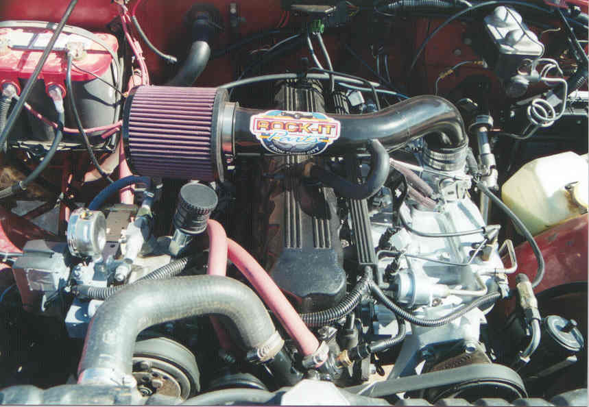
This is a 1990 4.0L engine from a XJ (Cherokee). HESCO supplied updated sensors, throttle body and harness from their Mopar MPI kit to upgrade the original Renix system. In November 2002 I relocated the air filter element to the right front fender near the grill to hopefully pull cooler air into the engine.
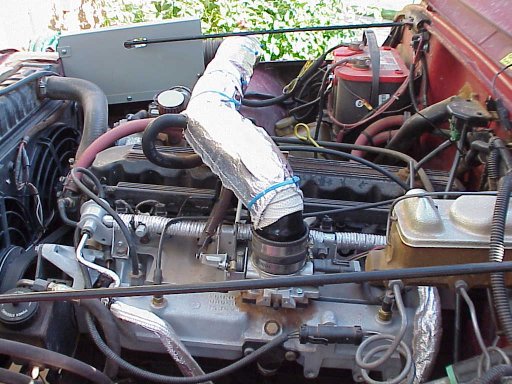
Relocated air filter and insulated air tube.
I had my ODBI scanner attached to monitor Inlet Air Temp sensor readings before and after this modification.
Out side air temp was 95*
Before re-routing and insulation, IAT reading was 220* @ 65 MPH
After re-routing and insulation, IAT reading was 180* @ 65 MPH
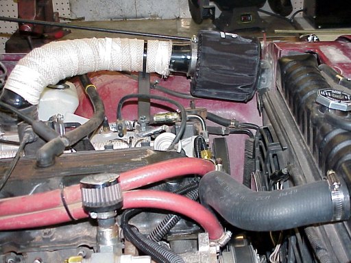
Relocated air tube and filter again in August 2003
Early stages of construction:
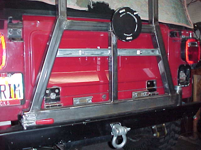
Left picture: Without gas can mounts and with short tire mount
installed.
Right picture: With gas can mounts and long tire mount installed.
The main horizontal pivot material is 2" x 3" x 1/8" rectangular tube. The remaining material is 2" x 2" 1/8" square tube. Wanting to keep the weight down, I used some of the 2" square tube for the tire mount to slip into. Then it was nearly impossible to find anything to slip into the 2" without modification. The can carriers were bought from Dick Cepek many years ago. It takes less than 10 minutes to remove the spare tire, cans, can mounts, and install the short tire mount and spare tire.
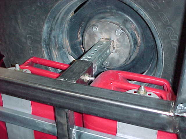
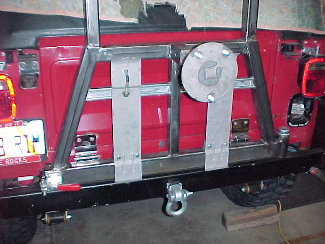
Left picture: Tire extended and cans mounted.
Right Picture: Side view of mounted cans and spare tire.
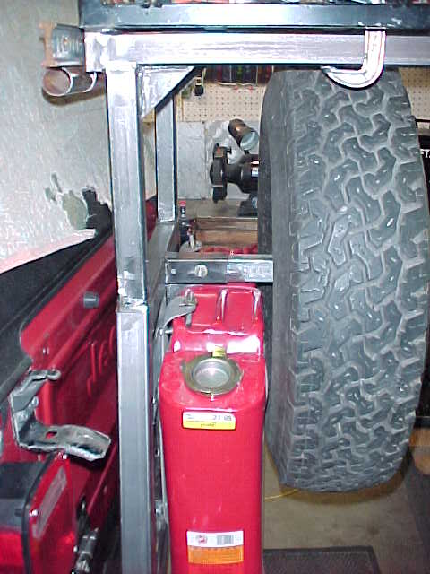
The overall design is for the upper arms to slip into the main swing away.
This way the cooler rack and the arms can be removed when not needed. In
real life, the pieces will probably rust together and become one. Oh well.
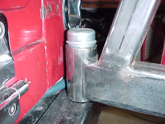
Left picture: Carrier pivot was made from a 1" trailer spindle
bought from Northern Tools,
part No. 12414W and a machined down 2" sch. 180 pipe nipple.
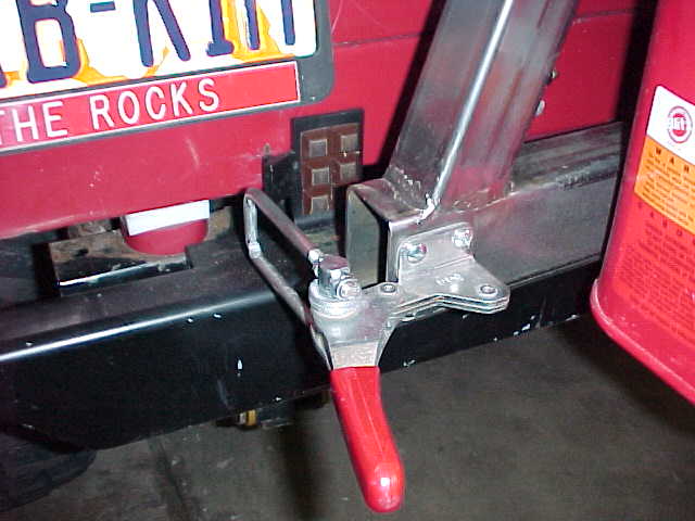
Right picture: Latch was bought from McMaster
Carr, part No. 5135A27. The catch mounted to the bumper is a 4" x 6"
1/4" plate bent at 90* and trimmed on the left for the latch hook. Generic
rubber bumpers from the hardware store provides some cushion.
The bumper was last years project. It's a piece of 2" x 4" x 3/16" rectangular tube. I welded two pieces of 4" x 3/16" channel to the back drilled to match the original 4 bolt holes per side. The rear cross member is reinforced on either side of the frame with 1/4" "L" shaped brackets. The center was cut out to recess the receiver tube.
THIS INFORMATION IS GIVEN "AS IS" AND WITHOUT WARRANTIES AS TO PERFORMANCE
OF OR ANY OTHER WARRANTIES WHETHER EXPRESSED OR IMPLIED. NO
WARRANTY OF
FITNESS FOR A PARTICULAR PURPOSE IS OFFERED. BY USING THIS
INFORMATION YOU
RELEASE THE AUTHOR FROM ANY
LIABILITY WHATSOEVER.