Bass guitar preamplifier in the Ampeg SVT tradition
Simulation of the preamplifier circuit with LTSpice IV
My simulation schematic does not include the high voltage or filament power supplies, and omits the balanced output transformer. It also leaves out a few components like the 10 M ohm resistors that bleed off the charge from various film capacitors in the ultra-low and ultra-high switched tone shaping networks to prevent switching pops. These don't substantially affect the simulation results and clutter the schematic. A rendering of the schematic may be found here.
I obtained the triode models for the 12AX7 and 12AU7 developed by Duncan Monro here.
LTSpice does not include models for toggle and multi-position selector switches. I created symbols and subcircuit models for the switches I needed using examples I found on the web. Here are the SPST symbol and subcircuit. Here are the 1P5T symbol and subcircuit. Symbols files go in your LTSpiceIV/lib/sym directory and subcircuit files go in your LTSpiceIV/lib/sub directory. LTSpice must be restarted before the components can be used. Setting the switch values is clunky. Right click on the switch symbol and set the POS= variable to the desired value. For the SPST switches, POS=0 is off and POS=1 is on. Set the 1P5T switch POS= values to 1,2,3,4, or 5 to set the desired switch position.
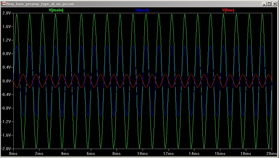
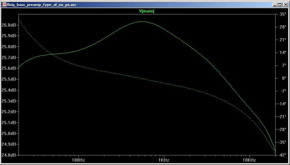
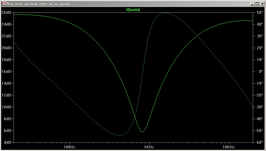
Please forgive me for not presenting a detailed LTSpice tutorial using my project. If you are trying to use LTSpice for the first time, first spend some time to find and go through the some of the many existing web tutorials created by more patient and knowledgeable people. I am not much more than a beginner. Mainly, I am able to use the transient simulation to verify the voltages, currents, and signal levels at each node in the circuit, and the AC analysis to obtain the expected amplitude and frequency response. You don't need to use simulation to build the project, but it helped me find errors in my layout before I built it, and was helpful debugging a few issues during construction.
I can't say how accurate the simulation might be in an absolute sense. I find the measured voltages, currents, signal levels, and frequency response predictions to be perfectly useful for designing and debugging the types of vacuum tube musical instrument and audio equipment I build.
A few simulation results