Bass guitar preamplifier in the Ampeg SVT tradition
Power supplies
Regulated filament power supply
| The regulated filament power supply
board is designed to supply 12VDC @ 750 mA. The
preamp contains 2 x 12AX7 and 2 x 12AU7 filaments,
each nominally drawing150 mA. The
regulator is good for 3A, and the filament windings
are rated for 2A. The limiting factor is the
heat sink dissipation. I consider this a
conservative thermal design, because at 750 mA and
40C ambient temperature, the regulator junction
temperature is less than 40C below its maximum
rating. The following description presents the
details. |
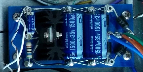 |
The power transformer I selected, the Antek AS-05T280, provides only 12.6 VAC under load from the filament windings, which is exactly right for an unregulated AC filament, but insufficient for a regulated 12V supply using the same diodes and regulator as the SVP-CL. To obtain a regulated 12 VDC from the Antek's filament windings, it is necessary to use both a low dropout regulator (LDO) and low forward-voltage-drop diodes. I chose MUR-410G diodes and a LM1085-12 regulator. The forward drop from the diodes is only 2 x 0.9V = 1.8V, and 1.5V from the regulator, giving a total DC drop of 3.3 V. Ideally, the minimum AC voltage for this arrangement to stay in regulation is (12V + 1.8V + 1.5V) / 1.41 = 10.85 VAC. We should therefore be able to stay in regulation With the AC mains 10% low, or 12.6 VAC x 0.9 = 11.3 VAC.
It is possible to obtain a 10 dB improvement in the regulator's ripple rejection performance by using the adjustable version of the LM1085, rather than the fixed version, because the adjustment terminal can be compensated with a bypass capacitor. Iteration 2 of the filament supply might use the LM1085-ADJ instead of the fixed LM1085-12 to take advantage of the better ripple rejection, and to allow the output voltage to be set to 12.6V instead of 12V, if desired. I don't think a few mV ripple is significant for a DC filament supply, and it is perfectly acceptable to supply nominally 12.6V filaments with 12V (5% low).
The regulator requires a heatsink. Given an input voltage of 16V, an output voltage of 12V, and an output current of 0.75A (4 x 150 mA filaments + 150 mA for margin), the power dissipated in the regulator = (Vout - Vin) x Iout = 3 W. The LM1085's maximum junction temperature is 125C. Therefore, we need a heatsink that can dissipate 3W with a temperature rise of less than 125C - T ambient. I chose to work the problem backwards, by finding the thermal resistance of a 1" high TO-220 heatsink (so it would fit in a 1U box), and calculating the thermal rise. I chose an Aavid Thermalloy 531002B02500G (Mouser part 532-531002B25G), which has a thermal resistance of 13.4 C/W, i.e., each watt dissipated into the heatsink will result in a rise of 13.4 C. So dissipating 3W will result in a rise of 40C. Adding in the thermal resistance of the TO-220 package (0.7C/W), and the thermal pad that electrically insulates the regulator from the heatsink (0.2C/W) gives a thermal rise of (13.4 + 0.7 + 0.2)C/W * 3W = 43C. If we let the ambient temperature inside the 1U box be 40C (104F), then the junction temperature will be 40C + 43C = 83C, which gives us a thermal margin of 42C before the regulator chip hits 125C. The vertical stack up of a 1" heat sink on a 1/8" board mounted on a 3/8" standoff doesn't leave any clearance between the top of the heatsink and the top cover of the 1U case. I gave it vertical clearance by using a 1/4" standoff in place of the 3/8" under the filament power supply board.
The negative terminal of the filament output is referenced to a voltage divider on the B+ supply giving 1/4 of the B+ voltage (77V). Raising the filament reference voltage reduces the heater to cathode potential for the direct coupled preamp stages.
The power-on indicator LED is driven through a current limiting resistor from the regulated filament supply. The 20 mA draw from the LED serves as a minimal load for the regulator if all the tubes are removed for troubleshooting.
High voltage power supply
| The high voltage power supply is
designed to supply 320 VDC @ 20mA for the B+ of the
preamplifier, and provide a well-filtered reference
voltage of 1/4 the B+ voltage (~80 VDC) for the tube
filaments. The high voltage winding of the Antek AS-05T280 supplies 290 VAC @ up to 90 mA to 4 x UF4007 silicon diodes forming a full wave bridge rectifier. The RC filtering stages are 3 x 47 uF electrolytic caps separated by 1.2 K ohm resistors supplying about 320 VDC @ 20 mA to the preamp board. Following these filter stages is a voltage divider consisting of a 100K and 33K resistors, supplying 77V to the filament reference. It is filtered with a 10 uF electrolytic cap. The voltage reference supplies negligible current. I followed a rule of thumb to keep the total resistance of the filament reference divider less than 150K. |
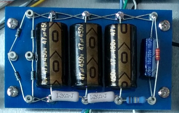 |
Ampeg's SVP-CL B+ supply used 3 x 100 uF
filter caps. I used 47 uF caps without any
misgivings because 100 uF @450V axial lead caps were not
readily available, and the additional capacitance is not
really effective for a circuit that draws only 20 mA (the
rule of thumb is 1 uF per 1 mA). The Ampeg design
feeds the next 7 preamp triodes from the same B+ node,
with only the first gain stage B+ being decoupled by
another 100 uF cap. This is a poor use of
capacitance, as a single 12AX7 triode draws less than 1
mA, leaving the other 7 triode sections with a poorly
decoupled plate supply. It is not considered good
practice to feed more than 2 gain stages from the same
power supply node, as the triode sections can have
undesired interactions through their common power supply
nodes, e.g. "motorboating". Even though this isn't a
high gain preamp, I still didn't like the idea of running
7 triode sections from the same power supply node.
My preamp board B+ supply uses a 10 uF / 6.8 K ohm RC filter for the first gain stage, a 10 uF / 1.5 K RC filter for the next 3 triode sections, and another 10 uF / 1.5K RC filter for the next 2 triode sections. Cascaded RC stages are much more effective at reducing voltage ripple than adding capacitance to fewer stages, as only a few nanovolts remains in the B+ supply at the critical first gain stage.
Because this unit will be used in Europe, a externally accessible voltage selector switch is provided. The voltage selector switch connects the dual primary windings of the power transformer in parallel for use with 120VAC mains, and in series for 240 VAC mains.
Simulating the high voltage power supply
As with all of my prior projects, I used
Duncan Amplification's Power
Supply Designer II, a free Windows application
that makes it easy to graphically design and simulate
typical unregulated linear power supplies in a few minutes
with a bit of pointing and clicking. You can achieve
the same result with simulation tools like LTSpice, but it
might take a few minutes longer starting from
scratch. Here
is my PSUD2 design file for the preamplifier's
high voltage supply. The output of the program looks
like this:
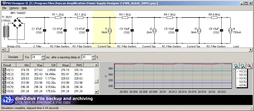
The tabular section of the output
shows the voltages and currents at each node of the
circuit. I've scrolled the output to the
voltages at each of the filter capacitor nodes.
The simulation results agree with the preamp as-built
to within a few volts. Note that the predicted
power supply ripple, Diff at V(C6), the first
stage preamp, is 176 nanovolts. That is what you
get from 6 cascaded R-C filter stages. The basic
rule of thumb for calculating what rectified DC output
voltage under load you need from the power transformer
is approximately 125% of the DC voltage after the
final filter stage. In this case, 376 VDC after
the rectifier is filtered down to 291 VDC at the first
gain stage. The loads are represented as fixed
current taps. The values of the fixed current taps are
the sum of the plate currents for all the tube
sections attached to that power supply node. The
plate currents may be obtained easily from an LTSpice
simulation of the preamplifier, using a fixed DC
voltage supply. I simulate the power
transformer, rectifier, and initial filter caps
separately from the rest of the preamp because it
takes the several seconds for the power supply to
reach steady state, much longer than the preamp
circuit.
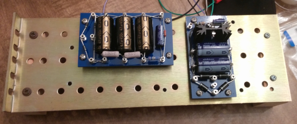
Constructing the power supply boards
Full-sized layouts are cut and taped
to the blank circuit board to serve as a template
for marking the positions of the screw and turret
holes. Note that some component values shown on the
layout templates were changed in the actual
build. Refer to the complete build layout
document for the correct values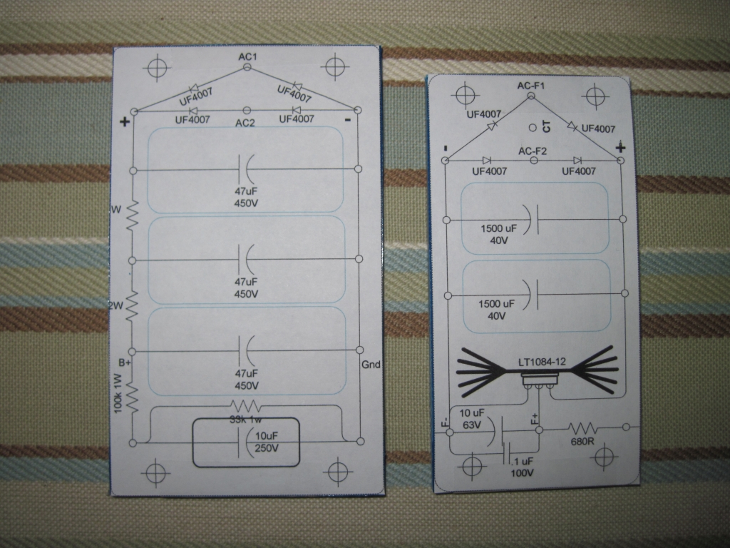 |
A spring loaded punch is used to mark
the locations of the screw and turret holes, then
the layout paper is removed from the boards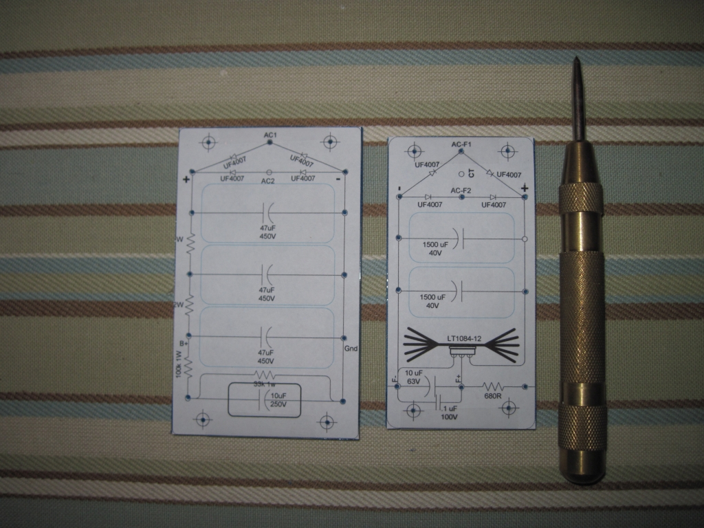 |
The boards are drilled on a drill
press. The drill size is #33 (0.113"), which
is just 0.001" larger than the turret body for a
very snug fit.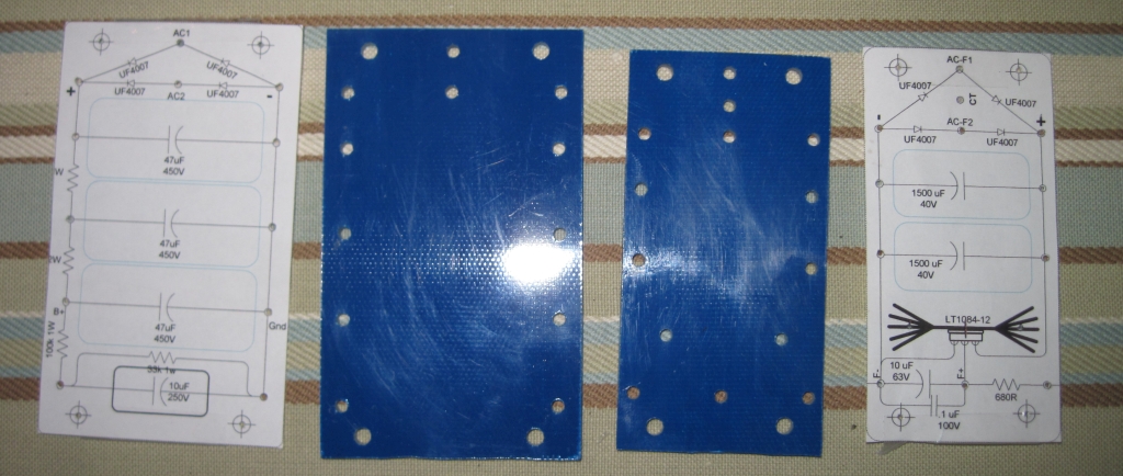 |
The turrets are swaged into the
holes. The Keystone turret lugs are Mouser Electronics
part 534-1509-4. I like using these turrets
because the large hole in the center can accomodate
several component leads. I set the turrets on my
drill press (not plugged in) using the Keystone
staking tool 534-TL-8, also available from
Mouser. I recommend using the Keystone tool
rather than a pointed DIY swaging tool, because the
profile on the Keystone tool flares the end of the
turret without damaging it.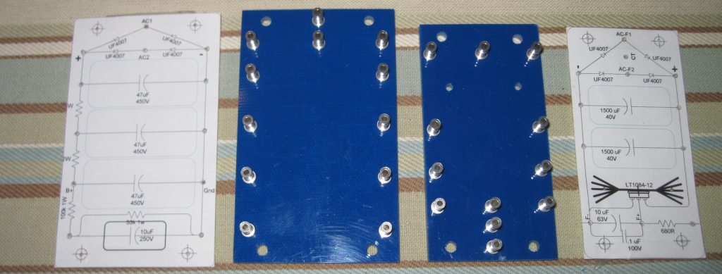 |
The appropriate turrets are laced
together with #22 soft tinned buss wire, using the
Doug Hoffman technique explained here.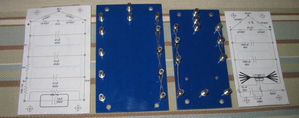 |