Bass guitar preamplifier in the Ampeg SVT tradition
Reverse engineering the multi-tapped toroidal
inductor
- the thickness of the magnet wire
- the size and material of the toroidal core
- the number of turns of wire for each tap on the inductor
I purchased an original Ampeg/SLM inductor
from an ebay seller. It was about half the cost of
the Mercury Magnetics part, and 3x the price marked on the
Ampeg service part bag it came in. In the remainder
of this section, I describe the process I used to
non-destructively determine the recipe for the Ampeg
inductor, and to hand-wind a duplicate myself for less
than $4 in material and a couple hours of labor.
To determine the thickness of the wire, I used calipers to measure the diameter of the wire near the start and end terminal posts: about 0.0170". The NEMA-MW-1000 magnet wire chart shows a diameter of 0.0170" for #26 single build magnet wire, and 0.0178" for heavy build (insulation thickness).
To determine the length of the wire, I measured its DC resistance: 1.7 ohms. Using the nominal 0.04089 ohms / foot resistance for #26 wire from the chart, we get 1.7 ohms / 0.04089 ohms/foot = 41.57 feet = 499 inches. Since this was measured on a couple of ordinary digital voltmeters, the length could easily be off by a foot or two.
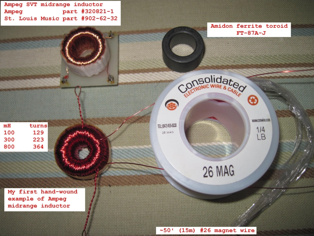
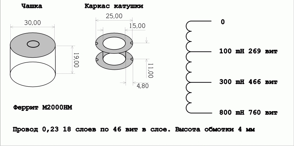
From the outer diameter (0.97"), inner diameter (0.40"), and height (0.55") of the wound Ampeg inductor, I deduced that the toroid core is most likely a ferrite size FT-87A (0.870" OD, 0.540" ID, 0.500" height).
Given this core size, I calculated the minimum wire length per turn is OD - ID + 2 x H = 0.87" - 0.54" + 2 x 0.5" = 1.33". Using Google Book search, I found a book McLyman's "High Reliability Magnetic Devices Design and Fabrication" (print ISBN 978-0-8247-0818-4) that gives a formula for Mean Length per Turn (MLT) for a toroid as 0.8 x (OD + 2 x H) = 0.8 x (0.87" + 2 x 0.5") = 1.50". At maximum, we compute 499" / 1.33" / turn = 375 turns. On this core size, #26 wire gives 92 turns / layer, so there will be about 4 layers on the core
I deduced that it's a ferrite core, and not a powdered iron or permalloy core, because to achieve an 800 mH inductance with a core of this size and fewer than 400 turns of wire, it has to be a ferrite material with much higher permeability than powdered iron or permalloy (MPP).
To determine which ferrite material type, I estimated the core's inductance (mH) per 1000 turns (called AL) from the nominal inductance and estimated number of turns. For ferrite:
# turns = 1000 x Sqrt(mH / AL)
375 turns = 1000 x Sqrt(800 mH / AL)
AL = 800 mH / (375 turns / 1000)^2 = 5689
The only common ferrite material in this core size with AL about 5689 is material "J". The Amidon catalog gives the AL for an FT-87A-J core as 6040. Solving for # turns with this core and material, we get: # turns = 1000 * Sqrt(800 mH / 6040) = 364 turns. This is close to the number of turns calculated from the estimated wire length and core size.
The predicted DC resistance, 0.4089 ohms / foot x (364 turns x (1.33"/ turn / 12 inches / foot) = 1.66 ohms. This agrees well with the 1.7 ohm measured value from the Ampeg inductor.
Calculating the turns for the 100 mH and 300 mH taps uses the same formula as above:
First tap @ 100 mH = 1000 x Sqrt(100 mH / 6040) = 129 turns
Second tap @ 300 mH = 1000 x Sqrt(300 mH / 6040) = 223 turns
Since all of the calculations made from simple measurements of the Ampeg inductor agree with theory, I was confident that my recipe for the tapped toroidal inductor is correct. I ordered 4 FT-87A-J cores and 1/4 pound (300 feet) of #26 magnet wire from the Crystal Radio Society, who provided good service and reasonable shipping! Amidon also has the toroids and magnet wire.
I wound 50' of magnet wire onto a shuttle I made from a 7" length of 1/4" wood dowel, and started winding down and clockwise. Two hours later, my first try at winding the SVT inductor was complete. The wind was not quite as tight as the machine-made original. However, the inductance values measured on an ESI 253 LCR meter were quite close to the design values: 95.6 mH, 295 mH, 781 mH. The original Ampeg inductor measured 102 mH, 290 mH, and 760 mH on the same instrument. There were 92 turns on the first layer, exactly as the toroid winding chart predicted. The next layers were less exact, as I was not able to lay the turns on top of the underlying turns so precisely. I also had no idea what the winding tension should be. This calculator [http://www.coilwindingmachines.eu/engineers_corner/tension.html] says 2 pounds.
The measured values of my DIY toroid are closer to the design values than Ampeg's part, I'm sure that it is good enough for rock and roll. Assuming the ESI 253 LCR meter readings were accurate, I calculate that a 4% overwind would probably hit the design values. My first tap, at 129 turns (same as nominal), was about 4% low. My second tap, at 227 turns (vs 223 nominal) was 2% low, and the final tap at 371 turns (vs 364 nominal) was 2.5% low. I added 7 more turns (378 total) to bring the final value to 801 mH. The DC resistance of my wind was 2.07 ohms, versus a predicted value of 1.93 for 378 turns. I doubt that a 5% - 10% difference from the design values matters much.
Making the tapped toroid inductor this DIY project taught me a lot more than I wanted to know about reverse engineering and hand-winding toroids. But it was worth the effort to enable DIY builders who want a lower-cost alternative to boutique part makers and ebay sellers.
To determine the thickness of the wire, I used calipers to measure the diameter of the wire near the start and end terminal posts: about 0.0170". The NEMA-MW-1000 magnet wire chart shows a diameter of 0.0170" for #26 single build magnet wire, and 0.0178" for heavy build (insulation thickness).
To determine the length of the wire, I measured its DC resistance: 1.7 ohms. Using the nominal 0.04089 ohms / foot resistance for #26 wire from the chart, we get 1.7 ohms / 0.04089 ohms/foot = 41.57 feet = 499 inches. Since this was measured on a couple of ordinary digital voltmeters, the length could easily be off by a foot or two.
From the outer diameter (0.97"), inner diameter (0.40"), and height (0.55") of the wound Ampeg inductor, I deduced that the toroid core is most likely a ferrite size FT-87A (0.870" OD, 0.540" ID, 0.500" height).
Given this core size, I calculated the minimum wire length per turn is OD - ID + 2 x H = 0.87" - 0.54" + 2 x 0.5" = 1.33". Using Google Book search, I found a book McLyman's "High Reliability Magnetic Devices Design and Fabrication" (print ISBN 978-0-8247-0818-4) that gives a formula for Mean Length per Turn (MLT) for a toroid as 0.8 x (OD + 2 x H) = 0.8 x (0.87" + 2 x 0.5") = 1.50". At maximum, we compute 499" / 1.33" / turn = 375 turns. On this core size, #26 wire gives 92 turns / layer, so there will be about 4 layers on the core
I deduced that it's a ferrite core, and not a powdered iron or permalloy core, because to achieve an 800 mH inductance with a core of this size and fewer than 400 turns of wire, it has to be a ferrite material with much higher permeability than powdered iron or permalloy (MPP).
To determine which ferrite material type, I estimated the core's inductance (mH) per 1000 turns (called AL) from the nominal inductance and estimated number of turns. For ferrite:
# turns = 1000 x Sqrt(mH / AL)
375 turns = 1000 x Sqrt(800 mH / AL)
AL = 800 mH / (375 turns / 1000)^2 = 5689
The only common ferrite material in this core size with AL about 5689 is material "J". The Amidon catalog gives the AL for an FT-87A-J core as 6040. Solving for # turns with this core and material, we get: # turns = 1000 * Sqrt(800 mH / 6040) = 364 turns. This is close to the number of turns calculated from the estimated wire length and core size.
The predicted DC resistance, 0.4089 ohms / foot x (364 turns x (1.33"/ turn / 12 inches / foot) = 1.66 ohms. This agrees well with the 1.7 ohm measured value from the Ampeg inductor.
Calculating the turns for the 100 mH and 300 mH taps uses the same formula as above:
First tap @ 100 mH = 1000 x Sqrt(100 mH / 6040) = 129 turns
Second tap @ 300 mH = 1000 x Sqrt(300 mH / 6040) = 223 turns
Since all of the calculations made from simple measurements of the Ampeg inductor agree with theory, I was confident that my recipe for the tapped toroidal inductor is correct. I ordered 4 FT-87A-J cores and 1/4 pound (300 feet) of #26 magnet wire from the Crystal Radio Society, who provided good service and reasonable shipping! Amidon also has the toroids and magnet wire.
I wound 50' of magnet wire onto a shuttle I made from a 7" length of 1/4" wood dowel, and started winding down and clockwise. Two hours later, my first try at winding the SVT inductor was complete. The wind was not quite as tight as the machine-made original. However, the inductance values measured on an ESI 253 LCR meter were quite close to the design values: 95.6 mH, 295 mH, 781 mH. The original Ampeg inductor measured 102 mH, 290 mH, and 760 mH on the same instrument. There were 92 turns on the first layer, exactly as the toroid winding chart predicted. The next layers were less exact, as I was not able to lay the turns on top of the underlying turns so precisely. I also had no idea what the winding tension should be. This calculator [http://www.coilwindingmachines.eu/engineers_corner/tension.html] says 2 pounds.
The measured values of my DIY toroid are closer to the design values than Ampeg's part, I'm sure that it is good enough for rock and roll. Assuming the ESI 253 LCR meter readings were accurate, I calculate that a 4% overwind would probably hit the design values. My first tap, at 129 turns (same as nominal), was about 4% low. My second tap, at 227 turns (vs 223 nominal) was 2% low, and the final tap at 371 turns (vs 364 nominal) was 2.5% low. I added 7 more turns (378 total) to bring the final value to 801 mH. The DC resistance of my wind was 2.07 ohms, versus a predicted value of 1.93 for 378 turns. I doubt that a 5% - 10% difference from the design values matters much.
Making the tapped toroid inductor this DIY project taught me a lot more than I wanted to know about reverse engineering and hand-winding toroids. But it was worth the effort to enable DIY builders who want a lower-cost alternative to boutique part makers and ebay sellers.