Obj: Map E Fields using Equipotential Lines
Materials: voltmeter, grid paper, conductivity paper and Ag ink
Mapping
Electric Fields
Obj:
Map E Fields using Equipotential Lines
Materials:
voltmeter, grid paper, conductivity paper and Ag ink
Procedures,
Analysis
I. Parallel
Lines
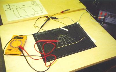
1. Obtain the conductive paper with the parallel
lines and a piece of grid paper.
2. Place your conductive paper on the board, then
hook up the electrodes as indicated on the sketch.
Set the voltmeter to 200 V DC.
Label the + and - electrodes on your grid paper.
3. Apply a potential difference of 5 Volts
between the two electrodes.
4. Begin mapping by using points to locate one
field line of equipotential at 1.0 Volts.
Using a pencil, connect the dots of this equipotential
line on your grid paper before going on to another line.
Continue with another equipotential line at a higher
voltage (for example 1.8 Volts).
The number of equipotential lines (6-8) should enable you
to draw the general pattern of the electric field E over the
entire grid paper.
5. Since the equipotential field lines are perpendicular
to the electric field lines, draw in the electric (E) field lines
using a crayon. (NOTE:
lines must not cross.)
6. Based on the volts (V) and distance (d),
calculate the maximum electric field (E) between your lines.
7. What force would exist on an electron placed
in your E field?
8. What acceleration would occur on an electron
given your calculation of force?
9. How much time would it take an electron to
travel from one line to the other under these conditions?
10. What final velocity would the electron attain
given the circumstances above?
II.
Another E Field Pattern
1. Obtain another pattern of conductive paper and
another grid paper. Indicate + and - electrodes. Plot out the
equipotential lines as you did above, then sketch in your E
field. Describe any
anomalies.
Back to the Brockport High School Science Department