Moonbeam: Therapeutic vacuum tube reconstruction for a guitar
amplifier and a man
I constructed this tube guitar amplifier using the chassis and speaker cabinet of a solid-state combo amp with several objectives in mind:
- Resume building tube gear after a five year interruption due a serious outbreak of real life
- Thin out the stock of tube amp parts I have accumulated in the past 7 years
- Recycle the chassis and cabinet of a solid-state guitar amp that sat unused in someone's closet for the past 10 years
- Do something useful with the prototype turret board I built
for my Moonlight
amp projects
- Build my younger daughter a guitar amplifier to take to
college
I enjoy all aspects of tube DIY design and construction: the circuit, the layout, the cabinet, etc. However, I don't consider myself a natural craftsman, so it takes me a lot of time and effort to perform the electrical and mechanical work to the standard I set for myself. I didn't feel up to taking on the whole load for my first project back, so I decided to improvise a useful amp out of stuff I just had laying around.
The main ingredients for this project were:
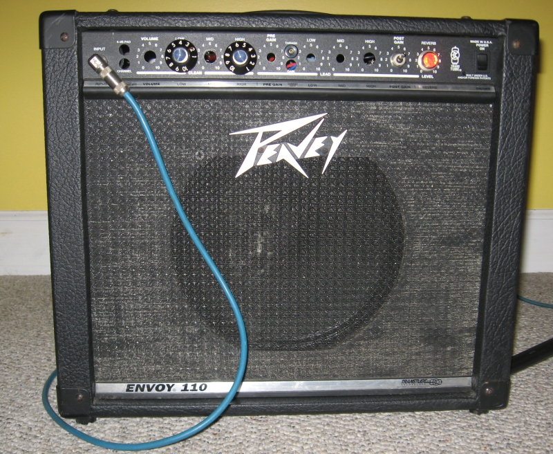
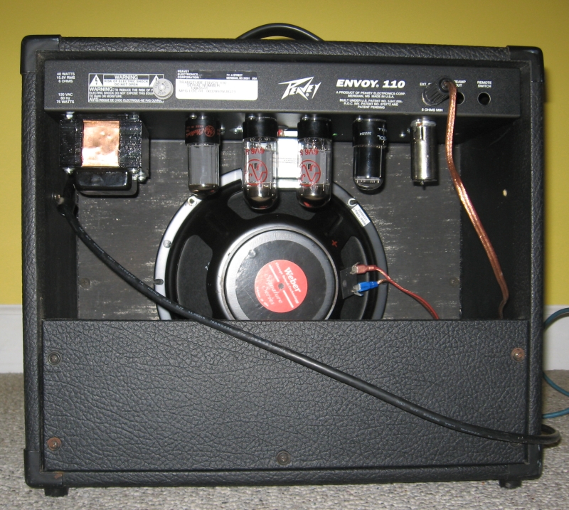
- A Peavey Envoy 110 solid-state combo amp that sat unused in my friend Gary's closet for 10 years, that wished to become reincarnated as a real tube amp.
- A "Deluxe"-sized power transformer, choke, and output transformer from Weber that I ordered about 5 years ago
- The populated turret board I built to prototype the AX84 Moonlight amp back in 2003.
Construction details
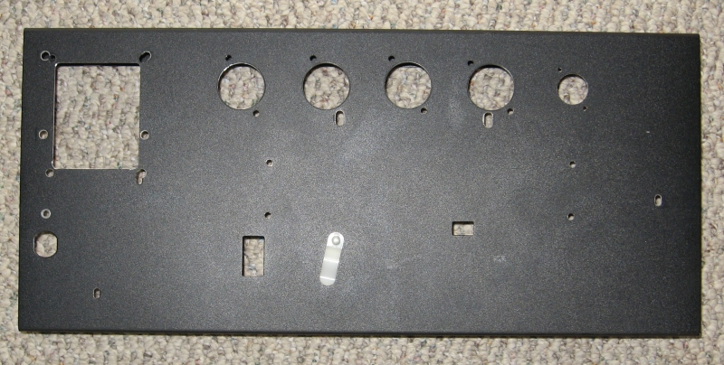
The back panel wasn't quite as perforated, but I did need to make a hole for the external fuse holder. The fuse for the original amp was inside on the PCB.
The circuit is essentially the same as my first Moonlight, with a power and output transformer appropriate for a push-pull 6V6 output stage. I hope you will forgive the lack of an as-built schematic. Here is a text description of the power supply and other important circuit elements:
- Connect 540 VAC (red-white) pair from PT to 5Y3 recto plates. The 680 VAC (red) pair and the bias (blue-red) lead from the PT are unused, insulated, and tucked away. First stage filter cap is 22uF/450V. Note: 5Y3 can't look into too much capacitance, the current inrush stresses it. The tube spec says 8 uF, but modern designs seem to go up to 32uF.
- Connect first stage filter cap to standby switch.
Other side of standby switch connects to output transformer center tap
(red) and input to choke (black). B+ to the center tap is 314 VDC.
- Output side of choke connects to second stage filter cap
(47uF/450V). The screen supply for the 6V6's connects here.
Each screen is fed through a 1500 ohm 2W current limiting
resistor. B+ to the screens is 302 VDC.
- Third stage filter cap (33uF/450V) connects to the second
stage by a 6800 ohm 2W resistor. The phase splitter plates are
fed here. B+ to the phase splitter is 273 VDC.
- Fourth stage filter cap (10uF/450V) connects to the third
stage by a 10K ohm 1/2W resistor. The preamp plate is fed here.
B+ to the preamp is 252 VDC.
- The 6V6's use a shared 330 ohm 5W cathode bias
resistor
bypassed by a
22uF/25V cap. Cathode voltage is 19.7 VDC. Idle plate
current to each tube, measured using the transformer shunt method is 32
mA. The static plate dissipation is (plate voltage - cathode
voltage) x plate current = (302V - 20V) * 32 mA = 9W.
- This power transformer has plenty of filament current and the 680 volt HV winding, so it would be no problem at all to run 6L6 outputs instead of 6V6's, or to run the 6V6's at higher voltages. To run 6L6's, the cathode resistor rating should be increased to 10W. A 6U4GB rectifier should replace the 5Y3GT (pin compatible, and the 5V filament winding has the 3A the 5U4 needs). Of course, the higher voltage transformer secondary will probably exceed the 450 VDC rating on the first stage filter cap, so we'd want a 500VDC rated cap there.
- Substituting a 5U4GB rectifier for the 5Y3GT increases all
the B+ by 20 volts.
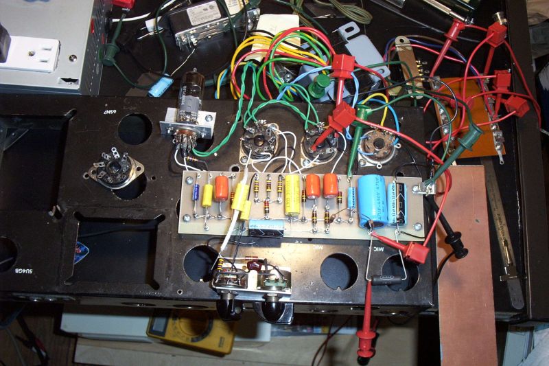
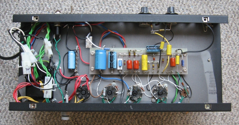
Here are the guts all wired up with transformers and switches
Debugging issues
Because I already knew that the turret board and sockets were wired correctly, I didn't spend as much time as I usually do checking my wiring before applying power. I checked the power supply up to the standby switch, ramping up the AC gradually on a variac and watching the voltmeter - no problems. The whole amp worked on the first try, but with fizzy distortion at low volume. I tracked it down to a loose resistor I hadn't soldered on the turret board. That solved, I cranked the volume and was quickly rewarded with the dreaded sound of high-pitched oscillation with the tone control anywhere near the treble side. I spent a while sifting for cold-soldered joints, bad grounds, and shorting grids and cathodes to ground with a cap, swapping tubes, and being perplexed. In desperation, I connected one side of the output transformer secondary to ground, and the oscillation disappeared. On the bench, I had connected the speaker to the OT's flying leads with test clips and no ground. I had planned to connect the speaker directly to the OT flying leads in the cabinet, but decided to obtain the necessary ground connection by running the leads back inside the chassis to a 1/4" phone jack mounted on the back panel. That seemed slightly less of a hack than running an extra lead back from the speaker to a terminal screwed to the chassis. Note the speaker jack is right next to the preamp tube socket, with the OT secondary leads close by. These are the kinds of things I normally go to great pains to avoid in my "careful" layouts, and I am happy to get off scott-free this time.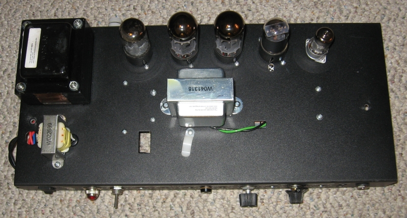
Tubes, from left to right: 5Y3GT rectifier, 2 x 6V6-GT output, 6SL7GT phase splitter, and EF184 preamp. The power transformer is the previous edition of the Weber W025130, with 120V primary, 540/680 VAC@150mA HV windings, 45V bias, and 5VAC@3A and 6.3VAC@5A filament windings. The output transformer is the Weber W041318 6600 ohm primary / 8 ohm secondary. The choke is the Weber W022699 9H@120mA.
What does it sound like?
In this amp, both strategies are effective. The 6V6's have plenty of headroom even with the high gain phase splitter, and can really accept a lot more useful (non-flabby) bass than a pair of 3.5W triodes. With the low-gain phase splitter, there's a couple more numbers of clean on the volume control for jazz-style playing.
It's not as bright as a blackface Princeton or Deluxe, which I wouldn't expect with cathode bias and the 320V B+ I'm running. It might sound 5E3-ish. When cranked, the distorted tone has the bluesy growl and singing sustain that makes it easy to get well-controlled fundamental and one octave higher feedback all over the guitar, something that I found it much harder to do with blackface-style amps.
It is conventional wisdom that pentode preamp tubes, e.g. EF86, EF184, can have microphonic issues in combo amps, because of the vibrations in the cabinet. It doesn't seem to be a problem for this circuit, though, probably because the pentode gain is set for the lower end of the possible range.
What next?
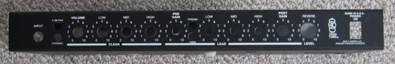
Cosmetically, a new control faceplate, speaker baffle, and grillcloth would de-Peavey-fy it to the point that someone might even think about stealing it. I'm not sure I can call it complete without attending to the cosmetics, but it's far enough along that I can start working seriously on the next build. And that was the main objective.
While doing the research for this project, I found a USA-made multi-tap output transformer to run 6K6's at the proper impedance ratio at Triode Electronics. They also sell a complete line of Fender-style power and output transformers from the same company (Magnetic Components of Chicago) at really good prices. While I decided to stick with the Weber transformer set for this amp, I couldn't resist picking up the similarly-sized set from Triode, along the a pair of JJ 6V6-S's. The Magnetic Components transformers arrived and look really beefy. I think they will be mounted on my next prototyping rig in the near future. Of course, buying another transformer set nullified the objective of reducing my amp part inventory, but you can't have everything. Where would you put it?