Bass guitar preamplifier in the Ampeg SVT tradition
Wiring jacks switches, tube sockets, and potentiometers
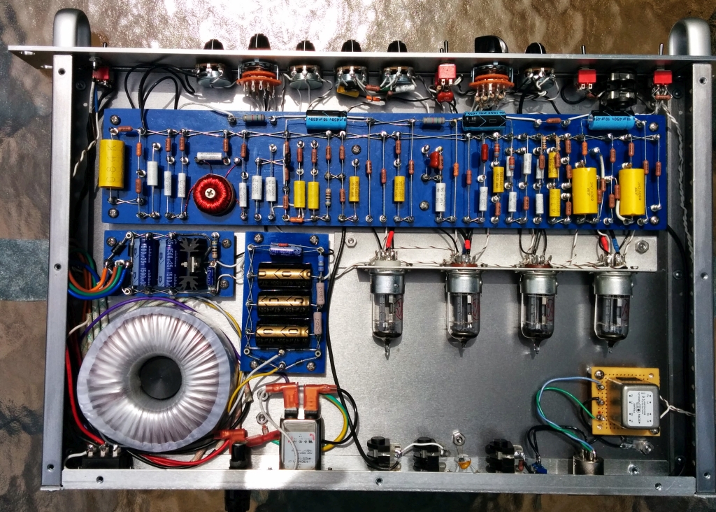
Important details about grounding and
isolation of the jacks, switches, and potentiometers
I followed several recommended noise prevention practices in
wiring the front and rear panel controls. All the 1/4"
input and output jacks are Cliff UK types, so the ring
terminals are isolated from the chassis. All grounds
to pots, switches, and jacks are wired directly to the
ground turret for the source or destination stage for the
signal. The only chassis signal ground connection is
made from the ground lug of the input jack. The ring
(ground) terminal of the output jacks have a high frequency
AC ground to the chassis through 1000 pF ceramic caps.
This effectively kills RF noise entering through the jacks,
as well as high frequency ground noise from the mains.
I have found that a properly sized RLC filtered IEC power
line entry module is essential for keeping mains line noise
out of the circuit, especially with a toroidal power
transformerInstrument input jack and pad switch
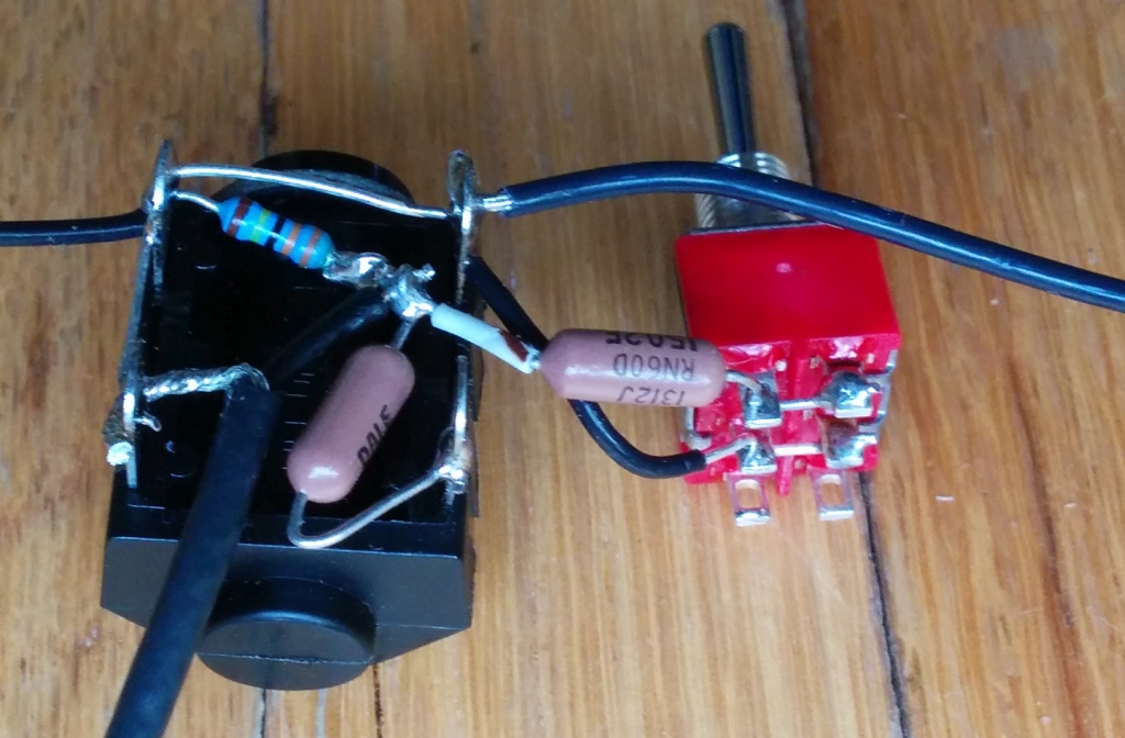
Here's the instrument input jack and pad switch. I used DPDT switches everywhere in the build, even when only an SPST switch is required electrically. That way you only have order one type of switch. When I only need one pole, I connect the second pole in parallel, to add extra reliability. The Ampeg schematic also seems to follow this practice with switches.
Tube sockets
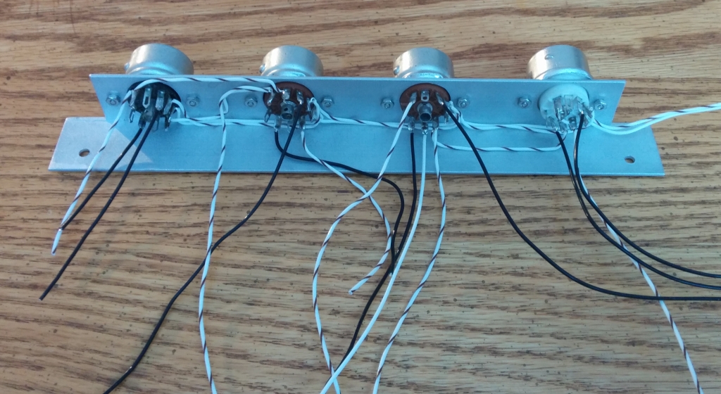
The tube socket holder is 1" x 1" x 1/16" aluminum angle stock from the hardware store. The holes for the sockets were made with a step bit. I solder flying leads to everything, except for the grid connections that will come on shielded cable later. I do the filament leads first. You can see them running along the bottom. Because I used regulated DC for the filaments, I did not twist the leads tightly, which would be standard practice for AC filaments.
Ultra-low selector switch
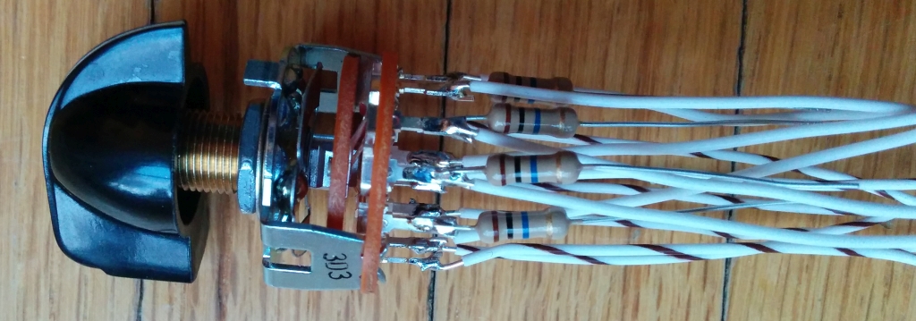
The ultra-low tone control selector switch is a 2 pole, 5 position switch. One pole sends the preamp signal to one of 5 tone-shaping networks, and the other pole collects the outputs. Note the 10 megohm resistors that connect to ground to bleed off charge from the caps in the signal paths that are not selected. These prevent a 'popping' sounds when the switching signal paths.
Connecting the tube sockets and ultra-low tone selector switch to the main board
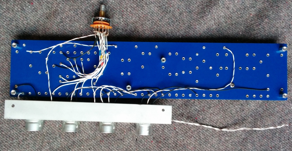
I solder most of the connections between the main board and the tube sockets and controls on the underside of the main board. The top of the board will appear very neat and clean, but connections under the board will be harder to service later. Good solder work is important to making the project reliable - I continue to learn the hard way! It is critical to trim the each flying lead to the correct length for where it will be soldered to the board. I like to use solid core wire for all these flying leads because it stays where you put it. The switches, pots, and tube sockets form a fairly rigid assembly that is installed and removed from the chassis in one piece! I install and remove the assembly from the chassis bottom plate many times during the assembly process, keeping each component aligned with chassis and control panel holes
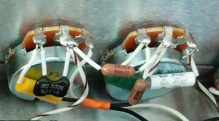
Bass and treble tone stack
| The bass and treble controls are of
the "James" type, and were wired with the
potentiometers attached to the front panel. I
might have preferred putting the tone stack on the
main circuit board, but I ran out of space.
Some builders may want to glue the capacitors to the
potentiometer bodies to minimize vibration pickup. |
 |
Front panel control fit
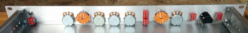
The vertical location of the front panel controls is critical in a 1U chassis. The Par-Metal chassis top and bottom panels have a lip that may interfere with various switches and pots. I mounted the potentiometers as low as possible to prevent the wiring at the top of the pots from creating a short circuit with the top cover. I would advise mounting them maybe 1/16" (~1.6 mm) higher to give the potentiometer case a little clearance from the chassis bottom.

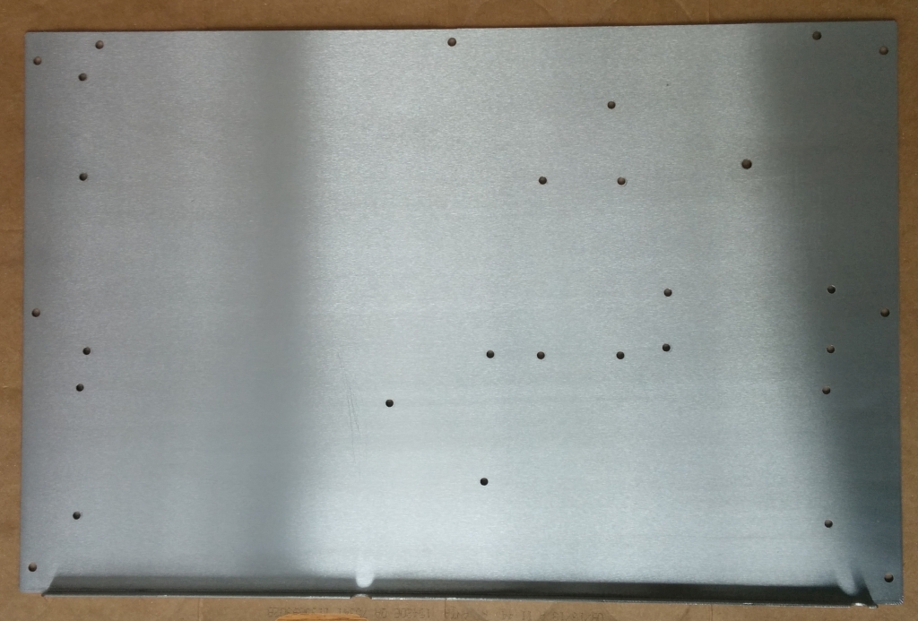
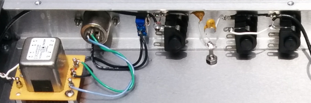
The rear panel is not that complex.
Note the 1000 pF ceramic capacitors forming an AC ground
between the chassis and ground terminal of the output
jacks. This practically eliminates RF and high
frequency buzzing noises from the mains from getting into
the audio.