Bass guitar preamplifier in the Ampeg SVT tradition
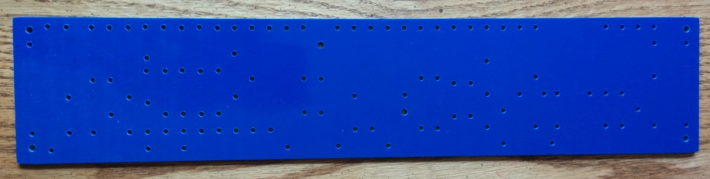
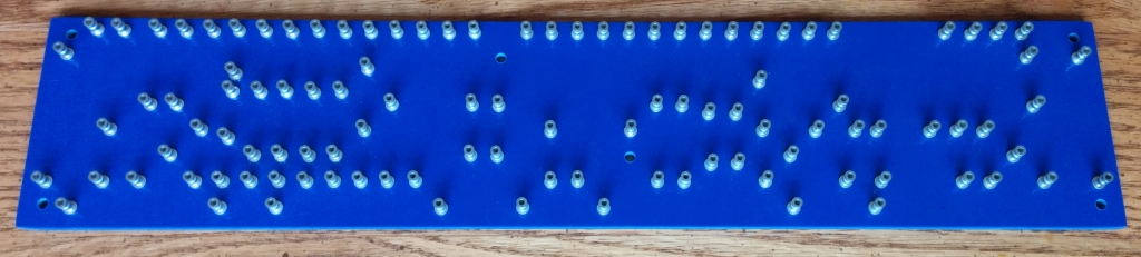
Layout and construction of the main turret board
Laying out and checking the turret board
design
The original SVT and SVP-CL circuits were built on printed
circuit boards (PCB's). Since I prefer to build using
turret board construction, it was necessary to design a new
layout from scratch starting from the factory schematic
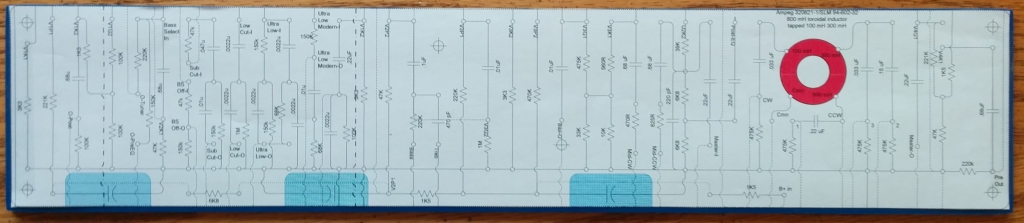
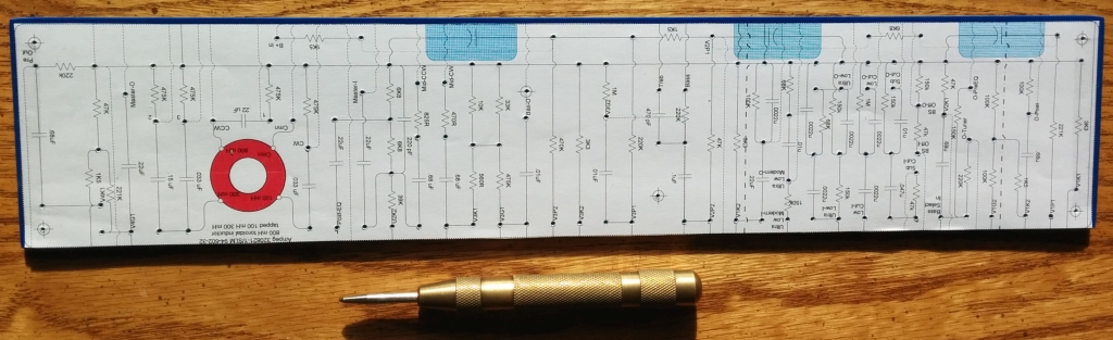
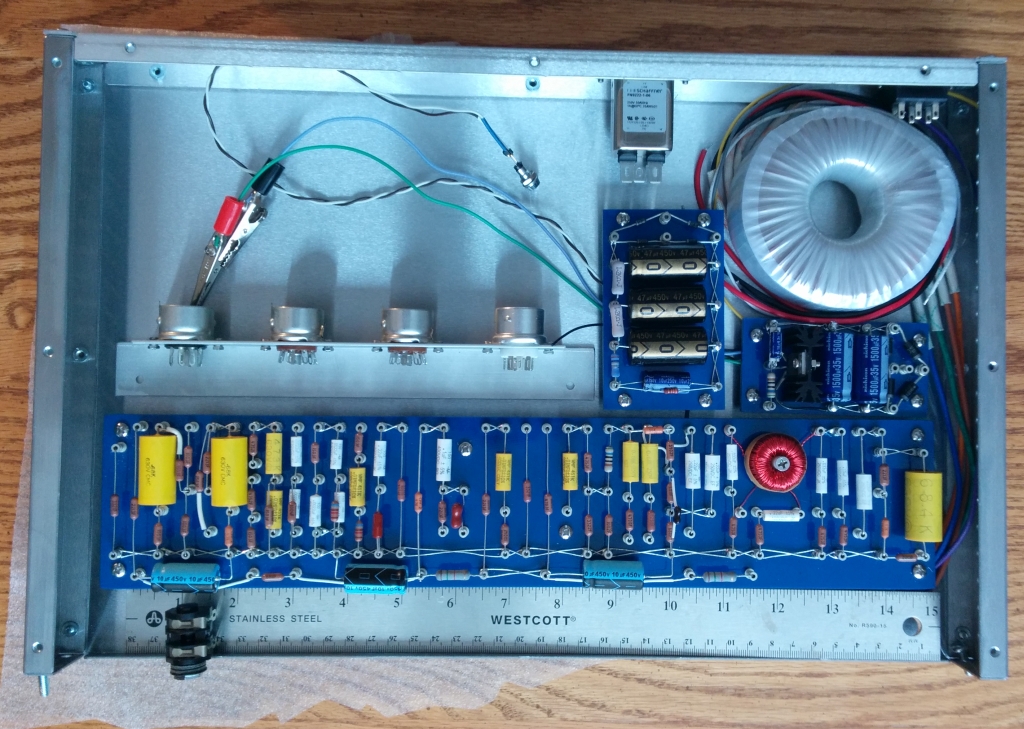
diagram.A turret board layout takes more space than a PCB layout, so I was not sure I would be able fit everything in the box using my normal circuit layout rules. It was a tight fit, but I got the whole preamp laid out onto a 15" x 3" turret board. The high voltage power supply and the regulated DC filament power supply are located on two smaller turret boards.
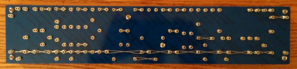
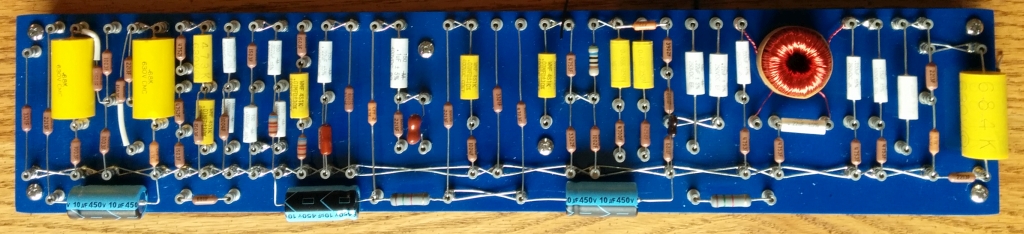
Using the factory schematic, I worked for quite a few evenings to lay out the preamp on a 15" x 3" turret board. I verified my layout by checking off each component and wire connection on paper prints of my layout and the original schematic. Then using my layout, I re-created the schematic in LTSpice, and verified the function of the entire circuit through simulation. The factory schematic for the SVP-CL did show a few unspecified capacitors and resistors. It wasn't that hard to obtain the unspecified values from the corresponding components on the original SVT schematic. I began the process of deriving the layout from the schematic somewhat mechanically, without attempting to understand the role of every component beforehand.. However, by the time I finished the painstaking process of building and checking the layout, then simulating the entire circuit, I understood practically every detail.
My preamp circuit layout used 108 turret terminals, and the two power supply boards used another 30 or so. There are roughly 80 components on the preamp board. I would recommend this project for advanced intermediate or more experienced builders. This layout, as with nearly all my previous projects, follows the style I adopted from Doug Hoffman. The bottom row of turrets belongs to the B+ buss, the next row is the ground buss, and the remaining turret rows are for the various signals. This preamp is so complex, the board is 1" wider than I have used before to accomodate 2 more rows of turrets than the 4 I required for simpler topologies.