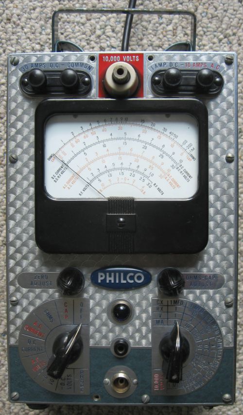
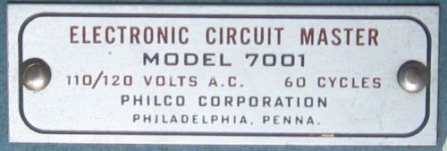
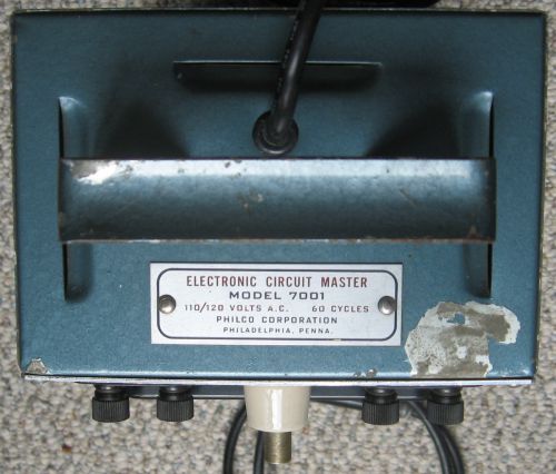
Restoring a 1947 Philco 7001 Vacuum Tube Volt Meter
(VTVM)
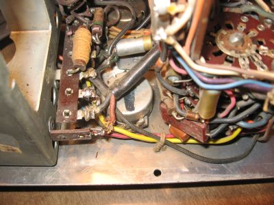
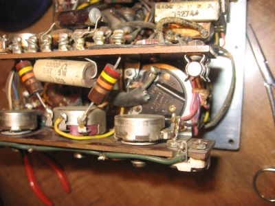
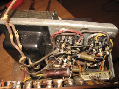
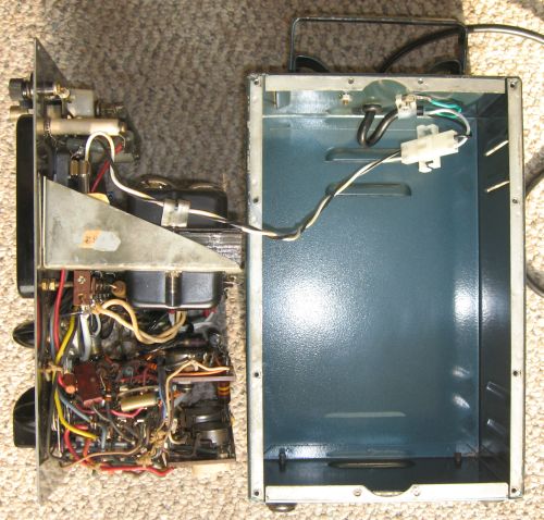
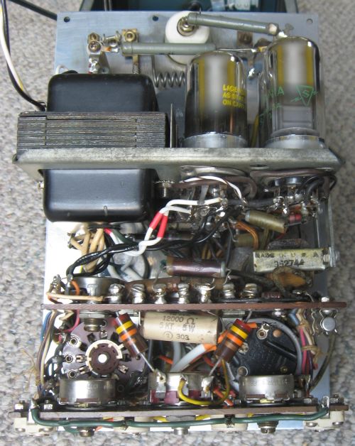
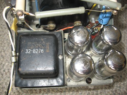
Filter capacitorThe power supply filter capacitor was a cardboard-sheathed single section 20 uF 450V twist lock FP type. While there were no signs of leaking electrolyte, I decided to replace it with a modern 22 uF 450 volt radial lead electrolytic attached to a new terminal strip fastened to an existing structural screw near the location of the original capacitor. Alternatively, I could have performed a more cosmetic restoration by attempting to reform the original capacitor, or replacing the contents of the original can with a modern cap. Since I preserved the original capacitor, I still have this option. However, I was more interested in determining whether the instrument would function well before I invested too many hours on appearance.Internal cleaningAs a side effect of having to detach the entire structure of the instrument from the front panel in order to remove the power transformer, I obtained much better access to the two bakelite terminal boards containing all the internal adjustment pots, wiring, and components that were not attached to tube pins and selector switch terminals. I cleaned the boards with numerous cotton swabs moistened with drug-store 91% isopropyl alcohol (IPA), taking care not to soak the cotton-insulated wire and custom-wound precision resistors on the boards. I hoped that the benefit of removing conductive dust from the boards outweighed the risk of damaging the wiring or components with the IPA.I treated the front panel zero adjust and range pots, as well as the two four-deck selector switches with Caig Deoxit. I carefully removed all old solder and bits of wire left on the terminals and tube pins from which I had previously snipped the wires. This is one of my least favorite restoration tasks, as it's a pain to manipulate soldering iron, solder wick, solder vacuum, picks, and tweezers in the cramped confines of point-to-point wiring. It's one reason why I'd rather scratch build new equipment on turret boards than restore old point-to-point wired gear. I worried that if the instrument did not work at the end of this modest restoration project, I might feel compelled to tear it apart and rebuild it to my semi-mil-spec standards. I imagined the excruciating tedium of desoldering and cleaning every terminal on the selector switches, and the worry vanished. Things left aloneOther standard steps when restoring antique electronics include checking carbon composition resistors for drift, and replacing all paper capacitors. Philco used good quality resistors in this unit, as all of the carbon comps were still well within tolerance. The manual emphasized the quality of the new (for that era) ceramic encased resistors used for all critical circuit elements. They were all spot-on. However, several tubular capacitors were tucked into relatively inaccessible locations, and I wasn't really sure what would make the best modern replacements. I hoped that Philco paid as much attention to the capacitors as they did to the resistors, so I left them alone until after functional tests and calibration. Also all the tubular caps are in low voltage dividing or compensating positions, so I reasoned that they might be less prone to DC leakage.I chose not worry about the tubes (7Y4 recifier, 2 x 7B5 bridge amps, and 6SN7 bridge) before testing the instrument. None of them are operated anywhere close to a limit, so apart from mechanical shock or a disasterous electrical stress, they should last forever in VTVM service. The meter movement was made by Simpson, another sign that Philco chose quality parts for this unit. The meter rectifier was a stack of four tiny copper oxide diodes. I hoped it was still in good shape. The outside of the case is finished in a hammertone dark turquoise enamel, with one signifcant chip missing from the paint, and plenty of smaller ones. It would be tempting to strip and refinish it back to factory, but not justifiable for this level of restoration. Once of the four felt-covered bottom feet was missing, and replaced with a washer and a #10 screw by the previous custodian. There are also 3 missing front panel screws, #6 x 1/2" slotted round head. Modern galvanized steel screws look too shiny. Stainless looks good with the chrome front panel, but I think that I will just scavenge vintage replacements from some non-restorable discard. These things can wait for my next outbreak of boredom, or a more fanatical restorer. |
|
Power on
I checked all the wiring from the mains cord though the PT primary winding with my DVM, then brought the instrument up slowly on my 2 amp variac while the VTVM lay uncased on the bench. No magic smoke escaped, no sparks flew, no smells emerged, and all the tube filaments glowed. The B+ showed 137 VDC (135 on schematic), and the meter movement fluctuated a bit, but did not crash violently into either stop. The filaments read 5.3 VAC (5.7 VAC on the schematic), but I know my DVM is off significantly on low AC voltages. The purple-jeweled pilot light indicated readiness to proceed.Basic function checks
Following the operating manual instructions, I tested resistors and capacitors in each of the ranges, and tested the +DC voltage on the 3V range with an alkaline battery. Good to better than 10%. It would need a run though the calibration procedure to do better, but I was satisfied that the instrument was pretty close to functionally restored. I spent another evening playing with the calibration procedure, but I will need a better reference instrument than my cheapie DVM to do a proper job of it. Ahhh, the days ahead....Conclusion
I'll call this restoration complete after one more pass though the calibration process with better reference sources and an HP bench DVM. I'll leave that for a future winter evening's recreation. With properly calibrated AC ranges, it will be much more useful than either of my cheapie DVM's. I re-learned how to read analog scales quickly enough while performing my casual calibration. This VTVM can take its place in with my other working vintage instruments, two Hewlett Packard 201CD signal generators and a Tektronix 556 dual beam oscilloscope. I also learned something about the theory of balanced bridges that are at the heart of VTVM's, LCR bridges, and so forth.One of the things I learned while researching capacitor reforming was that most, if not all cheapie DVM's and panel meters use the same analog chip that provides only 1 megohm input impedance, regardless of what the manual might say or imply. See this article at tubesound.com for all kinds of useful information about this. So the 15 megohm input impedance of this VTVM could actually be useful when I need to debug high impedance grid circuits (I use the 10 M ohm probe on my oscilloscope for these tasks). I'm tempted to buy or build a capacitor reforming rig also capable of measuring ESR and leakage at rated voltage. However, I don't really enjoy repair or restoration work as much as I do scratch building, so I'd just as soon not go there.
Completing this "simple" project was also a way for me to gauge my level of interest in restoring a Heath 10-12 oscilloscope like this one, also a hamfest giveaway. It works, so I already know that it's not completely dead (that means it's partially alive!). Replace the bad caps and drifted resistors and it's likely to be as good as new. Which isn't very good, as far as modern oscilloscopes are concerned. Restoring it would be another stupid labor of love, aside from the fact that I would learn more restoration skills that I don't really need, because I work too slowly to ever make money doing this for hire. Another useless thing I could do with this scope is install one of these in it, transforming it into a digital clock that consumes a 100W or so. But I digress...
Note that I didn't necessarily perform each restoration task in the order presented on this page. For example, I finished installing the mains cord last. I skipped around whenever I became stuck figuring out how to proceed.
Next project: restore my mad scientist lab so at least this stuff stays off my dining room table.