The Electric Table (Ver. 1.0)
I've
only seen a
couple of dinette table mount systems: The wall
hung,
swing bracket type and the two-post type. Both are
non-adjustable
in height, require physically lifting the table, and are either all the
way up up or all the way down. And
"up" is just too high for comfortable use of a laptop.
(I
never have gotten use to using a laptop on my lap.) , or, as we've
found with the current arrangement, too high for normal use.
Some
time ago, I made a
different kind of "manual" bracket that allowed intermediate height
positions but it still
required someone to physically lift the table. This is
difficult for the Mrs. There had to be a better
way...
The
following solution
seemed pretty frivolous at first but after thinking it over,
something invoving a motor seemed possible. That decided, I started
putting
the following prototype together.
Click
on picture for larger image.
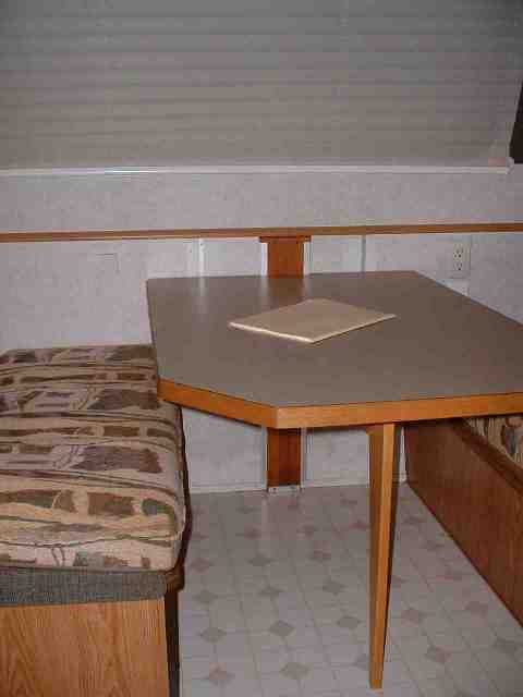
Here's
what the Electric Table looks like from a normal perspective.
To change the
height, operate a small toggle switch just under the front edge of the
table.
More on the
leg, below. |
 |
|
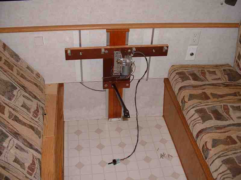
This
is the over all view of the hardware without the table. The
black
arm is a diagonal support made from 1/2" conduit that provides cantilever
support
when moving the table up
or down.
The table
top is screwed to the "T" bar in the back and connects to the conduit
near the
middle. See below for a better picture.
The cable dangling near the bottom ends
in a double-pole, double-throw,
center-off switch that reverses the motor for "up"/"down".
This switch is mounted under
the front edge of the table |
 |
|
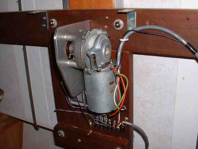
A view of
the right
side of the motor, a 24vdc worm-drive windshield wiper unit that
has plenty
of
power at 12 vdc to lift the table. Got it from a surplus
outfit
on-line. All the other stuff, unless otherwise stated,
is out of the hardware store or my junk box.
From
down in bed postition to maximum height takes 10 seconds. |
 |
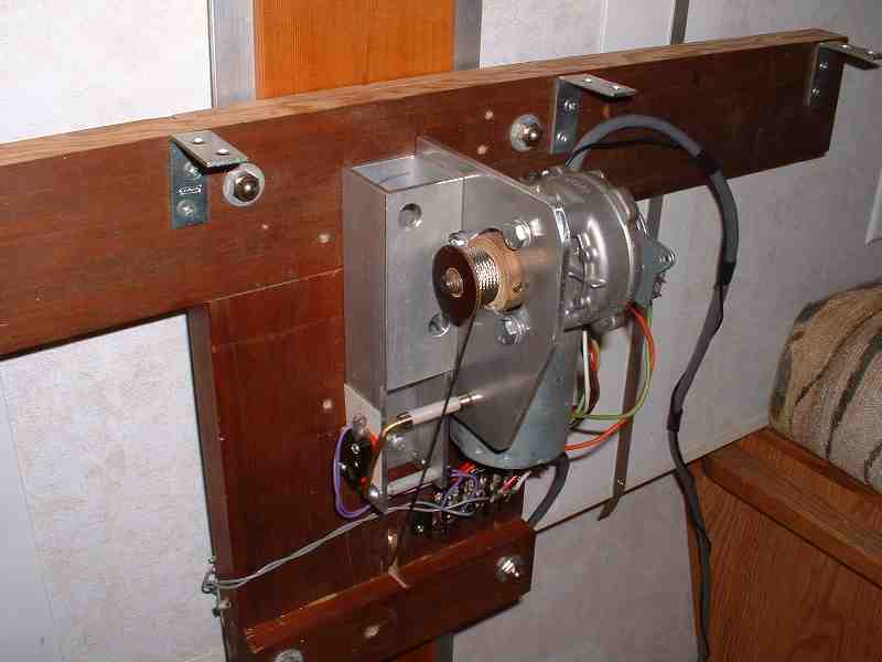
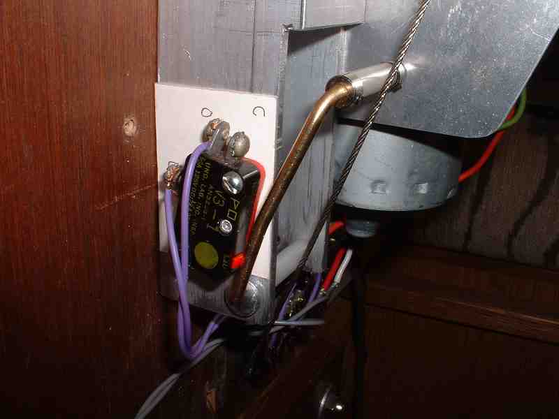
| Left
side:
100 lb test aircraft cable winds on a drum that is
set-screwed to
the motor shaft. The cable goes down, around the sheave near
the
bottom and up the back where it's secured to the rear rail support.
The motor thus travels with the table. The red and
black
switch is the down limit and is rigged to sense the cable tension.
If the cable slackens, either because the table is
down all
the way or hits an obstruction (like someones lap or a
cushion)
the cable relaxes, the follower releases the switch and the down
circuit is interrrupted. |
 |
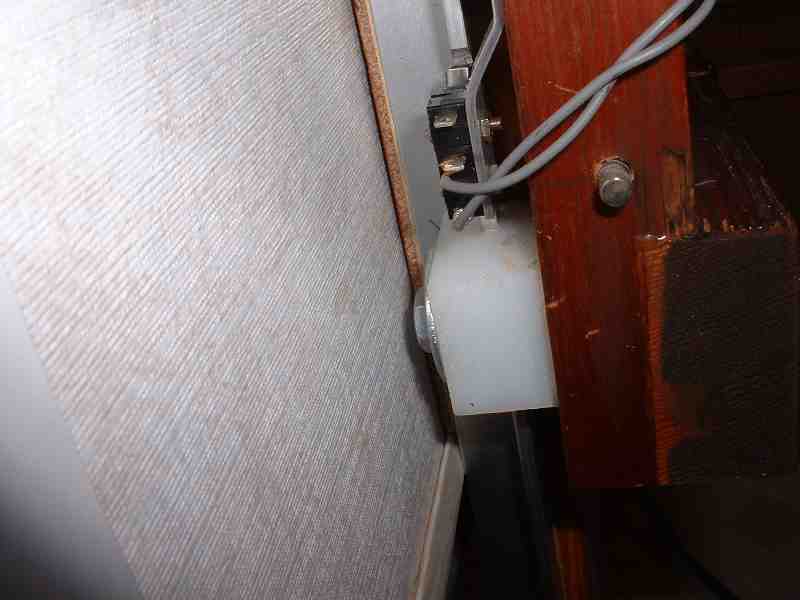
| A
closeup of the down limit switch. The white rollers reduce
wear
on the cable. The brass arm bends at 90 deg and pivots at the
bottom. The upper roller contacts the cable. It's
easier to
see how tension of the
cable keeps the switch closed until something obstructs the downward
table movement. Not shown is an auxillary spring that keeps
more
tension against the cable than provided by the switch. This
keeps
the cable from looping off the drum. |
 |
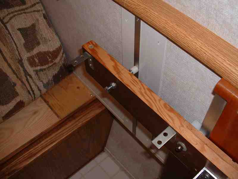
The
up limit
switch. I forgot to take a picture of this prior to
installing the assembly but it's just a
Radio-Shack micro-switch with a small roller arm. The roller
rides on the edge of the left rail and drops into a shallow dip where I
wanted it to stop.
Shown here is one of four slotted polypropylene blocks that slide on
the aluminum angle iron rails. I chose this mostly to avoid
having to mount a dozen rollers to restrict the carriage to
only
up-down motion. (It was
a prototype, afer all...) As it turned out, the blocks work
fine |
 |
| Here's
one of the two "wiggle stops" that help laterally stabilize the table.
They press lightly on two aluminum strips that are screwed to the
wall. |
 |
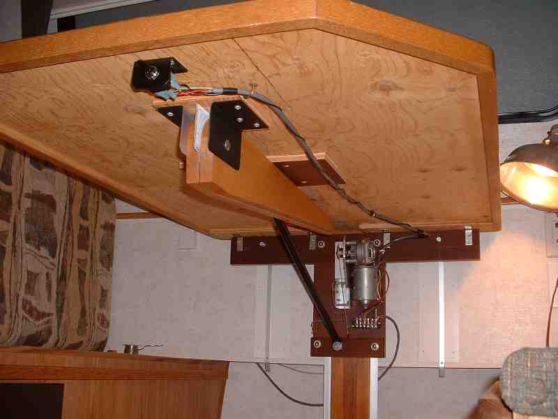
| A
view from beneath with the table installed. The two legs
folded
up are left over from the previous manually adjusted model.
Even
though the table is quite sturdy and works fine in cantilever mode,
I've decided to keep one of the legs in place and drop it down
when the table is being used
in the up position just to protect things from someone leaning or
sitting on
the table. The machinery is strong but the wall paneling is
not.
(See comment, below). |
 |
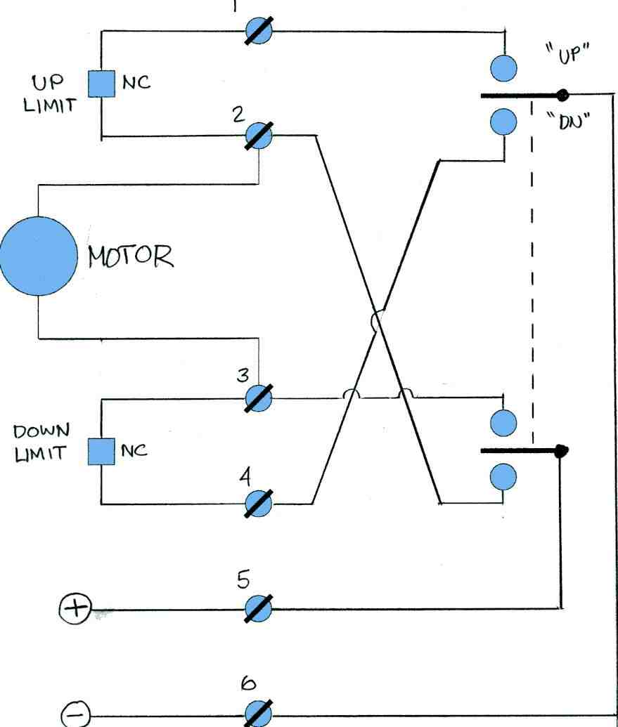
| Here's
the schematic for the rig, a standard motor reversing circuit with
limit switches. The "NC" next to the limit switches means
that
the contacts are "normally closed" when the switch is not being
activated, namely, when the table is not at one of the limits.
When a switch is contacted, it opens, interrupting current of
that particular polarity to the motor. Since the other limit
is
not contacted, reversing the switch reverses the polarity and the motor
can run in the opposite direction . . . until it hits it's limit. |
 |
Actually
the
whole thing turned out pretty well, a rare case where a prototype works
better than expected Unfortunately, the framing needed to
support
the regular table isn't sufficient to handle the kind
of
stress that a
cantilevered table can put on it. If I decide to
keep this
basic
design, I'll likely mount the whole thing on a piece of 3/4" cabinet
grade
(ie. flat) plywood and secure this to several more points on the wall.
No matter what, a powered table is the height of convenience when you
find yourself configuring your dinette for sleeping-eating-sleeping
.... etc.