A Large Inverter Installation

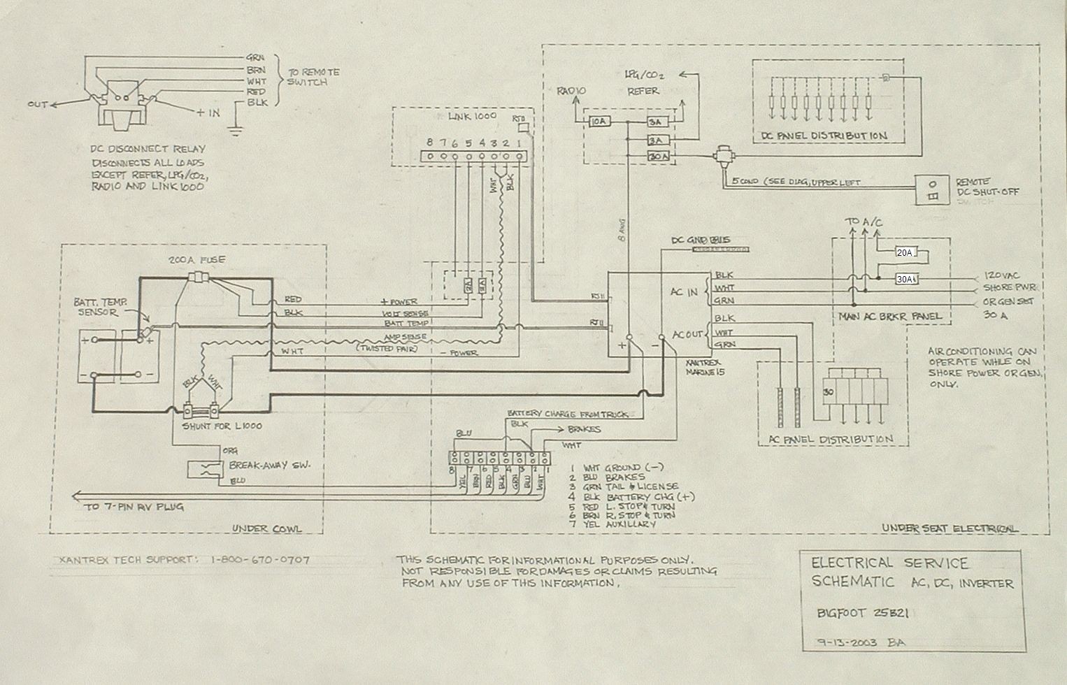
This is easily the most ambitious project to date. Some of the complexity was due to an extensive re-wiring of the front end electrical between the batteries and the new inverter.

Pictured is the original equipment Parallax converter. As you probably know, a converter converts AC shore power (120 volts alternating current) to about 13.8 volts direct current. This is used to run all the standard equipment that comes with the trailer. (Refer, water pump, hot water ignition, if any, lights, etc.) Thus, the converter powers everything DC while hooked up to shore power and recharges the battery at the same time. This is all pretty ok, so long as you don't demand a lot from your batteries (stay frequently at full hook-ups), and you never need AC power to your receptacles when boondocking. The problem is that most converters, and especially this one, don't know much about the care and upkeep of deep-cycle batteries. The technicalities are beyond the scope of this article, and, besides, there are numerous and better sources on the web that explain the intricacies of the subject. Suffice it to say, we decided to “improve” the situation.


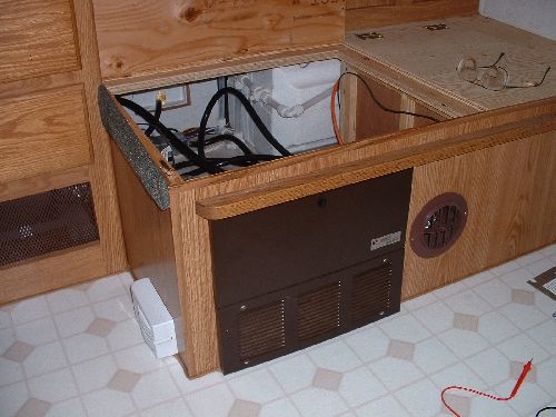
The Parallax, shown here without covers, is actually two things in one. The upper section is the load distribution part. The circuit breakers on the left protect the AC equipment and outlets, and on the right, automotive type fuses cover your DC circuits. This is all done up to UL code and works pretty well. The lower part is the converter itself. You can't tell much from here but the converter is pretty crude. That's ok, because it's going to go.

We decided to replace the converter with an inverter/charger. An inverter does the opposite of “convert”. It takes DC and “inverts” it to AC.  Thus, an inverter connected to your battery bank, will power your TV or other small AC appliances. I say “small” because, unless you have a really big battery bank, your batteries will deplete very rapidly. This is because most AC appliances use a lot of power compared to the usual DC tasks that need doing in your trailer. But what about re-charging the batteries when connected back on shore power? Our inverter, as do some others, has a very sophisticated charger built right in, one that understands in a highly competent way, how to maintain your batteries.  In adddition, it can charge your depleted batteries at a rate of up to 75 amps.  This makes short work of recovering from your two or three day boondock.


I forgot to take an outside picture of our inverter but you can find much more at http://www.xantrex.com , the manufacturer's site. Note that, from the guts, you can see it is a very well built piece of equipment with some serious electronics inside. Compare it with the picture, above, of the Parallax.

This inverter is a Marine 15. Go to the site, above, to learn more about these and other members of the Xantrex line. Over the years, this outfit has bought out most of its reputable competitors so that much of what is current inverter technology can be found in one place. They're not cheap but deals can often be found on eBay occasionally and at http://www.store4power.com/. This last site is the refurb outlet for Xantrex and is where we bought ours. Compared to retail, they have some very good prices that average about what eBay deals go for.

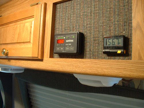
In my mind, these inverters have a huge advantage over their simpler cousins.  They have an optional monitor/controller panel that is, essentially a micro-computer (these days, what isn't) in a small housing with controls and a digital display on the front. They give you complete access to all inverter/charger functions as well as monitoring battery status and usage. Cool. I found a “Link 1000” unit on eBay for less than half the retail price.


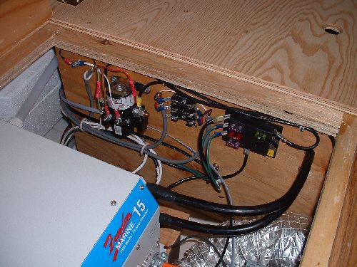
Before we could get started, I needed to figure out the existing wiring. For peace of mind, I decided I needed to know it all, from the front to the conveter. This meant that I had to trace out every wire through the various rats nests to my destination. In all fairness, Bigfoot probably doesn't expect anybody will be doing this so their emphasis is getting the job done ... not necessarily for show.  This is an area where a nicer job would assist anyone who has to work on the trailer, and improve the Bigfoot standing in the quality department.

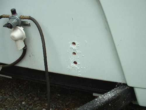
This is where the umbilical (trailer connection) comes up through the floor and into the trailer. The location is behind the under-seat area to the front left. The water heater is visible to the left.

I needed to straighten this out, as much as to know what was going on as to, well, just straighten it out.


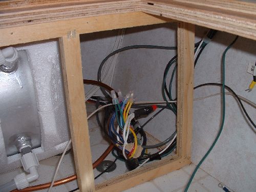
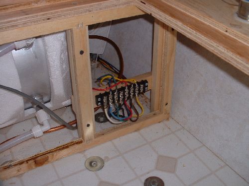
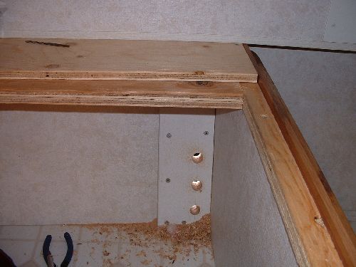
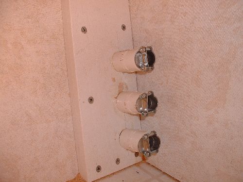
This was the result. Now, I know exactly what everything does, and where it is. The gray wire is the power and sense lines going from the inverter to the Link 1000 monitor, headed for the corner, then up inside the corner gusset into the top cabinet. The last picture shows the destination.

The panel I removed came out with a jillion little brads. It goes back in with four screws.


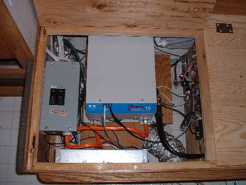
This is what the original “power cabinet” looks like. The lid is normally screwed on, something I rectified (using hinges) about 20 minutes after getting the trailer home from the dealer.

The silver snake is the 3” heater duct for under the table. It was completely in the way until I figured out to just to go over it.

The thick black wire is the 30 amp shore power line that normally is just stuffed through the power hatch from the outside.

We're looking down on the Parallax converter. The shiny part is the upper distribution section. The lower section with the fan is the converter section that will be removed. We gain 3 inches or so of room in doing that.


This is something every Bigfoot may not have. It's an option that is often packaged along with other stuff. It's a battery disconnect and is shown here in the original location in the forward under-seat area against the front wall, tucked up under the ledge. The umbilical terminal strip two pictures back is immediately to the left.

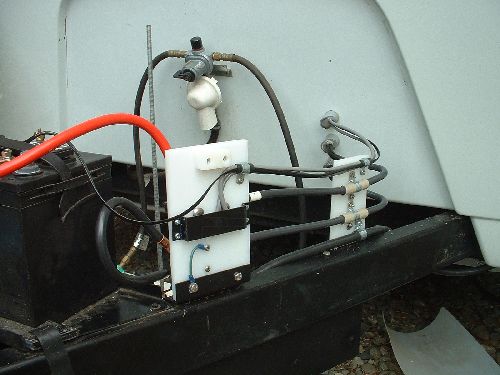
The disconnect relay is controlled by a rocker switch by the front door. I've heard a couple of explanations for this gizmo but the one I think is right is: it's supposed to disconnect the battery line to the towing vehicle so you don't discharge your towing vehicle starting battery while parked and still hooked up. For some reason, this one was wired wrong and disconnected the trailer battery from the trailer.  When the switch was off, then the refrigerator and anything else that needed to stay on, was also off.  The splices are where I originally connected the refer line direct to the battery to avoid the above.

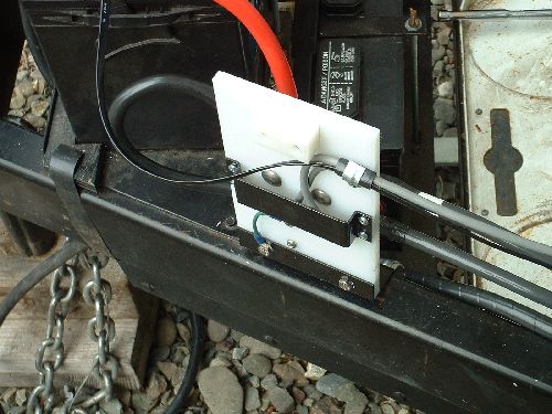
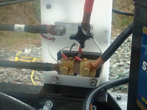
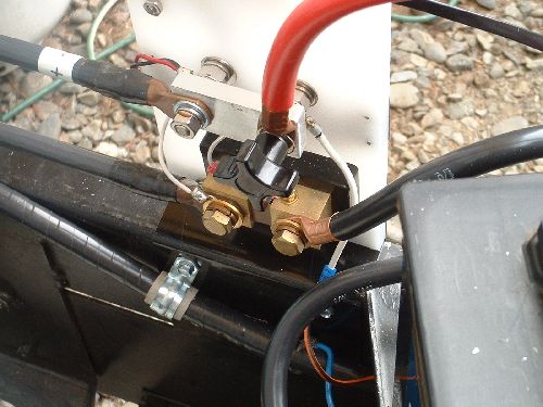
The fuses are for the main DC (30 amp) service from the battery, then split into one, for the refer, stereo circuit, and CO2/Propane sensor.

By now, I was getting pretty confident as to what everything was, and what I was going to do to it.


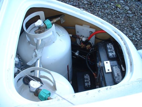
I had a 46 lb. Inverter with a footprint of around 12” by 14” that wouldn't fit around the duct. These are 4 x 4 redwood blocks lagged to the floor. On top of these, a piece of 3/8' ply gets screwed for the base of the inverter.


Here's a series of pictures showing the highly traumatic (measure 30 times, drill once) holes-thru-the-fiberglass operation from the outside, which will be under the cowling, and from the inside. Short stubs of 1/2” pvc are epoxied into the holes with romex clamps on the inside to secure the wires. The two bottom holes are for the main wires going to the battery, the top one is for sensor and control wires from the inverter shunt to the Link 1000 monitor.

The lower right picture shows the two number 2-0 wires from the battery to the inverter. Yep, 2-0. Just about 1/2” in diameter and capable of carrying 200 amps. This is a bit of overkill as I really only needed two 1-0 wires. Our building supply didn't have 1-0.

...Which brings up another point. The stuff I used is standard service entrance wire used in buildings. It's relatively cheap but only has a few strands so is very stiff. Normally it's around $1.25/ft. I got this even cheaper because it had been scuffed up. An option, which I used later on around the battery, is the wire used by automotive battery shops. It has hundreds of strands and is considerably more flexible. It cost more (around $2.00/ft) but the added flexibility makes it much easier to work with. Recommended.


This is the underseat “power cabinet” area. All of the electrical stuff has been rounded up and installed here. For lack of anything else to do with it, I installed the battery disconnect here, also, but all it does is shut down most everything but the refer and the propane sensors. We never use the thing so I probably wouldn't bother with it again. The center fuse block protects the Link 1000 electronics and the right fuse block is the "DC Main" breaker, 30 amps to the DC distribution panel down below. You can better see what is hooked up to what by looking at the schematic (linked to) at the bottom of this page. Re


This is what the finished under-seat area looks like. The gray box to the left is the new main AC circuit breaker. Shore power enters the top, goes through a 30 amp breaker, and is split. One line goes through a 15 amp breaker to the air conditioning (thus preventing it from working except on shore power. A/C simply draws too much power to run off an inverter/battery combination.) The other line goes to the inverter input (orange 10-3 wire going into the left side of the inverter). This allows the inverter to know when there is shore power and supply AC from that source when it's available. The inverter output (orange wire out of the right side) then goes to the old Parallax AC distribution center, where there just happens to be another 30 amp breaker (the old main breaker) which connects up to all the AC circuits. The second 30 amp breaker isn't really needed but that's how the panel is built and I didn't want to modify anything that was UL approved. There's a schematic of how this all comes together at the end of this article.


This shows the exterior “plumbing”. The white stuff is a polystyrene cutting block from K-Mart. I needed a cheap (there's that word again) easily workable material that was also a good insulator.

The “holes” are now PVC conduit couplings cut at 45 deg. and stuffed with Dicore putty tape.


The small block to the right is just a support for the wires.


A closeup of the forward block. As before, the top line is for sensing and power to the Link 1000. The line that drapes over toward the battery goes to a battery temperature sensor for the Link 1000. It connects to the plus terminal of one battery and senses the internal battery temperature. This information is used by the charging circuit to provide the highest charging current that won't damage the battery.

The black strap screwed in place protects the wires from chafing by the cowling.


Here's the inside view. The knob lets me easily remove the positive battery wire for a complete battery disconnect. The aluminum bar right behind it is a shorting bar where a 200 amp fuse will go (when it arrives from Stor4Power to replace the one I destroyed. I won't tell that story unless prodded pretty hard :-)...)

The brass looking thing is the shunt for the Link 1000. This is a very accurate and very low ohm resister. The two smallers screws on top connect to the sensing wires to the Link. When current flows through the shunt, a small voltage develops which is directly proportional to the current. This is routed to the Link 1000. ALL power to and from the batteries goes through this shunt so the Link 1000 can keep track of all current flow to and from the batteries. This enables the Link to calculate, keep track of, and display the amp-hours available, the instantaneous voltage, current, and other data. You can also start or stop charging and inverter operation, and initiate equalizer cycles when needed.


Notice that there is only one wire connected to the battery side of the large fuse: the one going to the emergency disconnect brake switch.  (White spliced into the orange/black.)  (Reminder:  My "fuse" in this picture is the solid aluminum block.  The picture was taken prior to receiving my real fuse.)

All the bolts and other hardware are stainless-steel.


Finished cowl area. I have a sheet of flexible plastic I slip over the batteries so the water that runs down over the lower lip of the door is diverted away. Just visible is the new 200 amp fuse.

The inverter is capable of a continuous 1500 watt output. That would drain the batteries quickly as it draws around 140 amps in the process.

When we get a better set of batteries, I expect to be able to report on using this the way it was intended. Meanwhile, with a little over two weeks continuous living with the inverter, I'd have to say it's already a success. When hooked up to shore power, the batteries charge in short order, (up to 75 amps.) much faster than via the truck alternator. In addition, knowing where you are in the discharge cycle (beyond the erratic and unreliable “monitor” panel that comes with the trailer) is pretty nice.


Success, and no smoke. The Link 1000 works perfectly. The wiring goes up behind and to the left, then down inside the corner gusset behind the paneling to the floor then back behind the seats to the power cabinet. Somewhat tricky to get it there.

One thing you can do with an inverter with this capacity is make toast.  Not the dry crunchy crouton stuff that comes out of the broiler, or the singed, hardly cooked-but black anyway variety that comes off the top burner, but real, actual, TOAST from the toaster. After doing it a few times, I have to caution that it's pretty expensive, power-wise, but it works.  You need shore-power, a long drive, or some generator time to restore you battery charge.

Important noteWhen boondocking, you must ensure that your refrigerator is set on GAS, not AUTO.  If not, the refer will see 120vac present and try to use that.  This will drain your batteries in short order.  A better solution is to change that 20 amp breaker shown going to the air conditioner into a duplex (double) breaker of 20/15 amps.  The 20 amp side goes to the A/C, the 15 amp side goes to the dedicated refrigerator circuit.  This puts the refer on the same terms as the A/C:  AC power is only available to it when connected to shore power.  This may require a new wire going from the breaker to the refrigerator receptacle, depending on how your trailer is actually wired.  I need to do this and will edit this section when I do. 


I don't have a snazzy CAD schematic of the final layout, but I do have a jpg of my hand drafted copy. It was originally 11x17 but prints out pretty well on 8-1/2 x 11 paper, landscape mode. The 245k file can be found here: http://www.frontiernet.net/~arbill/bigfoot/schematic.jpg


Please note that I'm not responsible for what you do or try to do with anything on the schematic or on this website. Use at your own risk. I would, however, love to hear from anyone who has success, feedback, or new ideas.