Motivation
Test Setup
FSK Excitation
AFSK Excitation
Measurement Method
Bandwidth Measurements
FSK Bandwidth
AFSK Bandwidth without waveshaping
AFSK Bandwidth with waveshaping
Waveshaping with the K3 PA
FSK through 400 Hz TX filter
Effect of K3 AFSK filter
Does any of this matter?
Real contest signals
Hearing the difference
General Conclusions
How can things be better?
This article investigates the transmitted RTTY spectrum using different modulation methods. The motivation has little to do with the timeless debate of which keying method is better (soundcard driven AFSK vs. OOK of the internal FSK tone generator in the radio), but rather has everything to do with spectrum usage in a crowded contest environment.
This investigation tries to answer the following questions:
This experiment looks at both a transmitter's internal FSK generator and various forms of AFSK transmission as well as power and TX filter bandwidth, since all of these are ways to generate an FSK signal at RF. I chose the K3 because it is a popular contesting transceiver that has both an internal phase-continuous FSK synthesizer as well as several configurations for transmitting AFSK. The K3's transmitted IMD is probably a little worse than some other popular contest radios (we'll see why this matters in a moment), but on the whole much of the analysis here is equally applicable to other radios. I will try make note of things that may be radio-specific as we go. I address FSK waveshaping for the purposes of reducing bandwidth, but not the issue of SNR degradation due to such waveshaping. This research is ongoing, although I have good reason to believe that the methods used in this study do not result in any meaningful loss of SNR at the receiving end. (A much bigger factor would be what kinds of filters--both software and hardware--that are being employed on the receiving end, but that is a topic for another day.) In practice, most contesters are listening through a 500Hz or narrower filter, so any keying energy transmitted outside this range is wasted anyway.
The reader is encouraged to draw his or her own conclusions from the data I present here. I also recommend reading W7AY's RTTY sideband discussion for an overview of different methods of generating FSK.
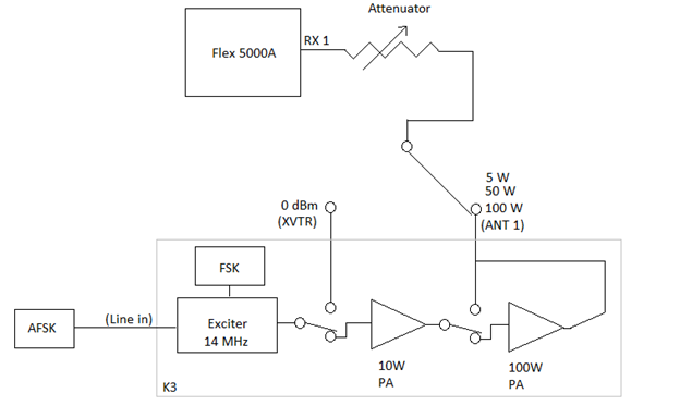
The test setup used an Elecraft K3 transmitter and Flexradio Flex 5000A used as a spectrum analyzer. The K3 transverter configuration was adjusted to transmit on 14 MHz which allowed bypassing the radio’s internal power amplifiers. A variable attenuator was placed in line to keep the signal strength constant at the receiver.
FSK excitation was generated with the terminal function K3 Utility software. The radio was set to use FSK-D. The transmitted data consists of a continuous string of “RY” at 45.45 baud with 2 stop bits. The data clock is entirely contained inside the K3 and does not rely on the Windows timer as it would with external FSK keying.
AFSK excitation was generated from the following software configurations:
The transmitted data consisted of a continuous string of “RY” at 45.45 baud with 2 stop bits. Ten seconds were sampled using the “peak-hold” spectral display in the PowerSDR software. The sample does not include keying on/off of the transmitter to avoid any spectral contamination (“pops”) by the beginning and ending of the transmission. In all cases the relative power seen by the receiver was kept 30dB below full scale by using a variable attenuator. All plots represent the spectrum of an equally strong signal from the point of the receiver and well below the clipping level of the A/D in the Flex (approximately S9+40dB or so).
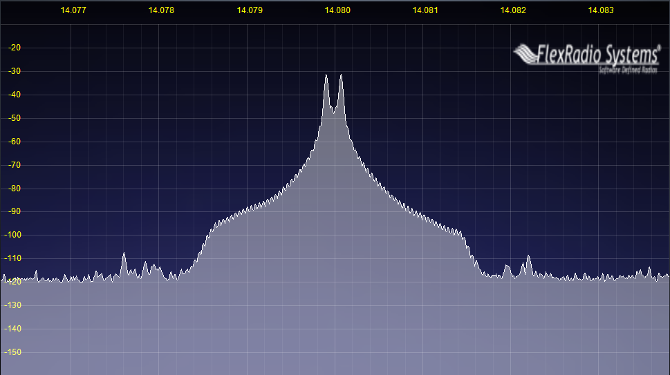
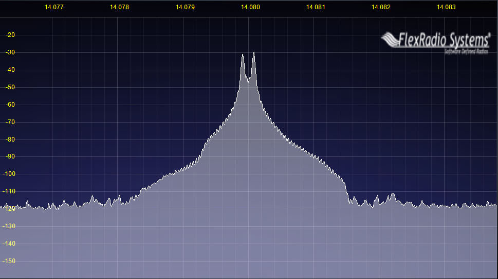
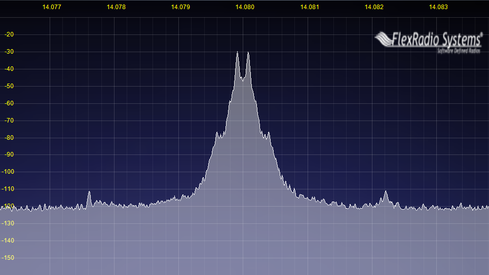
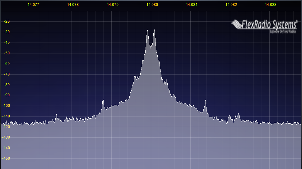
The internal FSK generator does not perform any shaping of the RF waveform. It appears to be phase continuous, i.e., it avoids instantaneous jumps in voltage at the beginnings and endings of bits. The spectrum rolls off at about 6dB per octave, which is what we would expect for this keying waveform. In FSK-D mode, the K3 places the signal in the middle of the IF filter. One can see the “knee” at +/- 1400Hz where the 2.8 KHz filter stops the sidebands from continuing.
In practice there is very little difference between the FSK spectrum with and without the PA chain. Since there is no waveshaping of the signal and therefore no overlap of mark and space tones, transmit IMD ("splatter" in the conventional sense) is not a factor. Notice the second harmonic energy at about 2.2 KHz from the carrier. This could be due to numerical precision of mark and space generator or a DSP artifact somewhere in the system. This is about -78dBc, so it is not likely to be a problem to many people.
|
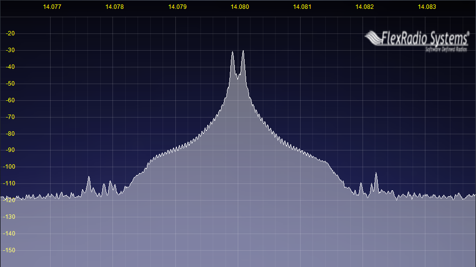 |
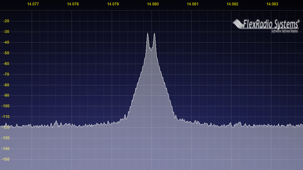
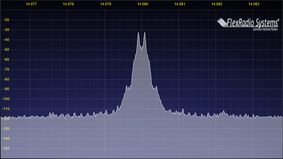
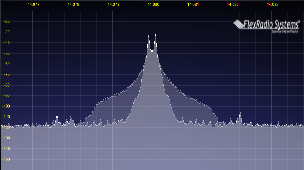
With no waveshaping the AFSK signal bandwidth, like that of the internal FSK generator, is limited by the bandwidth of the of the TX filter in the K3. Even with the AFSK TX filter disabled in the K3 it still places a lowpass filter on the audio spectrum with a cutoff around 3KHz, which explains the asymmetrical spectrum. This is something that is likely radio specific, and other radios will likely have a slightly different spectrum depending on exactly where the tones lie in relation to the IF filter. (FlDigi and 2Tone, as of February 2013, shape their AFSK output by default.) If there is no shaping of the bits in the AFSK modulation then the signal will be identical that of the FSK generator
 |
 |
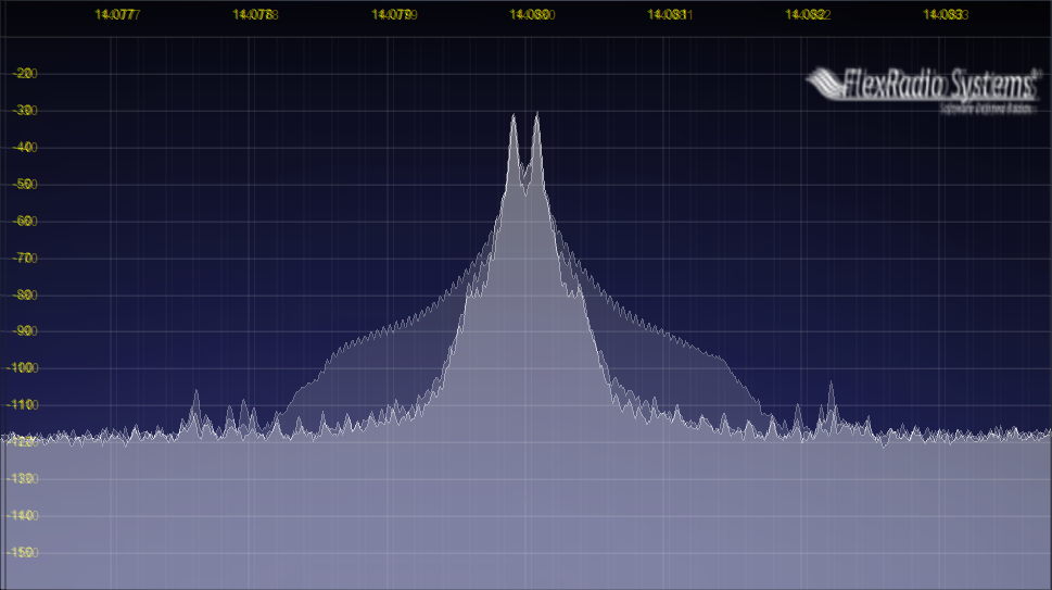
I investigated various waveshaped AFSK waveforms to reduce the bandwidth of the transmitted signal. Waveshaping can be thought of as altering the rise/fall times of the tones, much like shaping CW to reduce key clicks. (It may be helpful to think of RTTY as two on-off keyed signals 170 Hz apart.) Waveshaping can also be accomplished by passing the tones through a carefully chosen narrow filter. From that point of view, the "ringing" of the filter shapes the mark and space tones. No matter how one conceives of waveshaping, the net result is an amplitude envelope over the mark and space tones that applies a rise and fall time the the mark and space bits. This reduces keying sidebands in the same way that shaping a CW signal reduces key clicks.
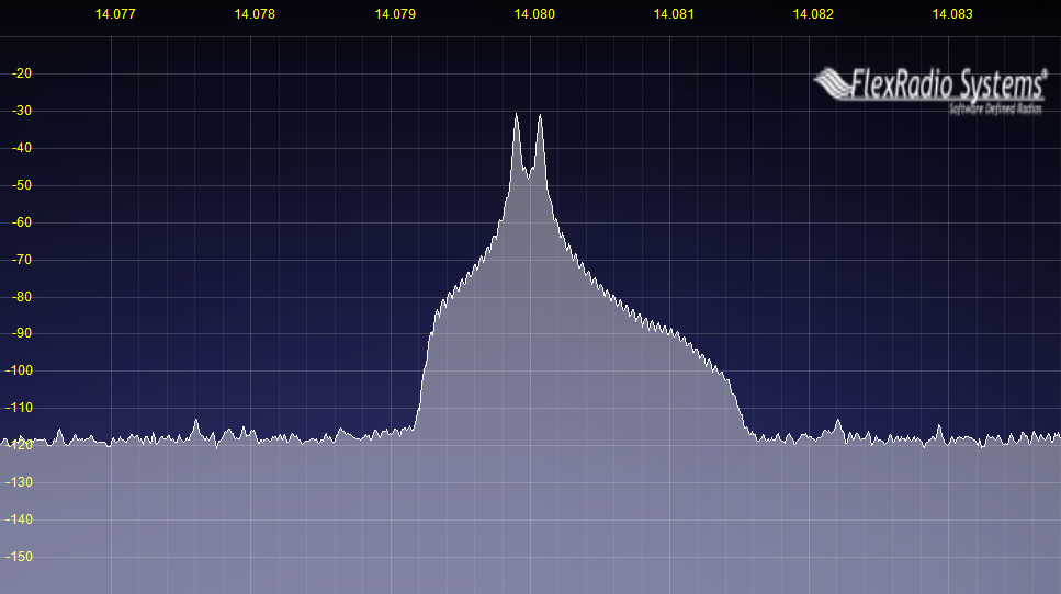
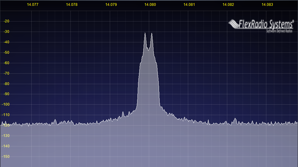
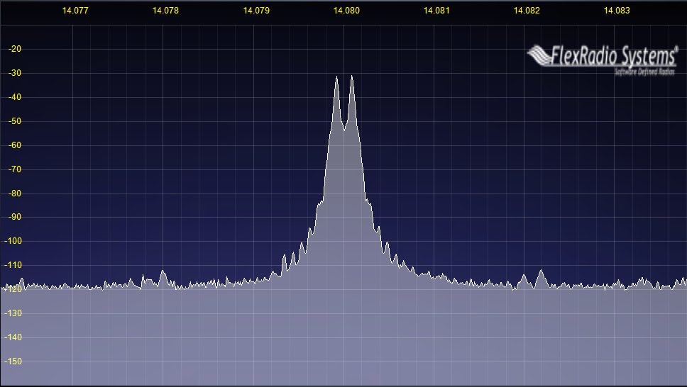
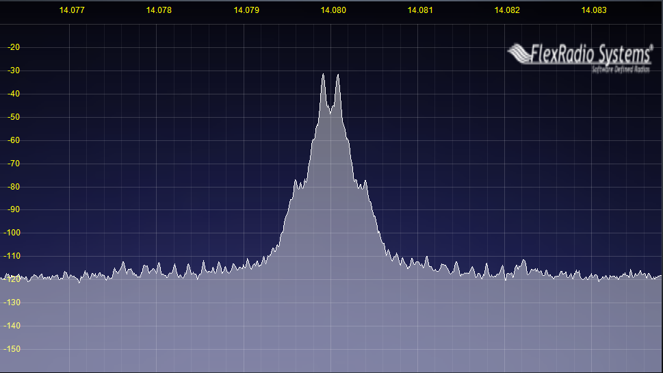
A few pieces of RTTY software do some waveshaping by default. The default setting in MMTTY uses a 48-tap filter centered on the transmitted tones. The net result causes a (very) slight overlap of mark and space pulses due to the "ringing" of the filter. Figure 5 shows the transmitted spectrum of this waveshaped signal from the K3 exciter. This is quite an improvement over the unshaped waveform. Figure 6 shows a more aggressive filtering using a 512-tap filter. This filter appears to be a Blackman window with a passband from 2000-2400 Hz.--essentially a "brick wall" filter in DSP that is 400 Hz wide. Figure 7 shows the waveshaped output from G3YYD's 2Tone software with the default "AM" setting, which is also a waveshaped signal.
 |
 |
 |
The spectra above show that the bandwidth of a signal can be reduced significantly using waveshaped FSK, at least when the transmitter is relatively free of transmit IMD. Because the waveshaping causes an overlap between mark and space during the bit transitions, the IMD of the amplifier chain can potentially undo some of these savings. Like all radios, the K3's exciter is not perfect, and you can just start to see some of the IMD sidebands coming into play in some of the plots above. When we run the K3 at "normal" power output, we begin to see the spectrum degrade. Interestingly, the K3 appears to have better 3rd-order IMD at 50W than it does at 5W, while the final PA may be contributing more to higher-order IMD. This is probably due to the 10w driver amplifier being driven in a more linear region. This will vary from radio to radio, and many "competition grade" radios will have better transmit IMD performance than this.
 |
 |
 |
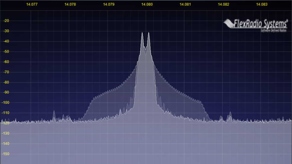
An important point to notice is this: Even with the transmit IMD of the K3 the spectrum using shaped FSK is much narrower than the internally generated FSK synthesizer. The chart below shows the spectrum of MMTTY, 2Tone and the internal FSK generator of the K3 at 0dBm and 100W output. One can see that even with the K3's IMD at 100W there is significant spectrum savings available. (Thanks to W7AY for putting together the composite images.) The FSK keying sidebands are not unique to the K3--every radio that uses unshaped keying for its internal FSK generator will generate a wider spectrum like this at pretty much any power level. The only differences will be in where the IF filter cuts off the sidebands.
 |
 |
As an experiment, I decided to see just how wide I could make my signal by overdriving the K3's line input. I cranked up the PC's headphone output to full power and drove the ALC hard as I could by setting the line input gain to maximum. Figure 13 shows the resulting spectrum. There are some strange spurs that show up in the spectrum, but notice that even these are below the keying sidebands from the FSK transmitter (refer to Figure 2). Even with the intent of transmitting absolute trash I wasn't able to make the AFSK signal become as wide as the internal FSK generator. The rise in the noise floor over the 2.8 KHz bandwidth is due to the K3 amplifying some noise from somewhere--at this gain setting it is present whether or not there is anything plugged into the K3's line-in jack. This behavior is almost certainly specific to the K3 because the K3 scales audio in DSP before it ever enters the RF stages. Other radios are not going to protect you from yourself nearly as well as this, and one would expect to see harmonic distortion and other bad things if there is no limiting before the RF modulation stage.
 |
One way to waveshape an internally generated unshaped FSK signal is to transmit through a narrower filter at the IF frequency. It is possible to trick the K3 into transmitting through the 400 Hz roofing filter. Early versions of the K3 firmware allowed this, but it was later disabled. If one is careful to center the tones in the filter passband one can transmit a much narrower signal and still use a keyed FSK key line or the internal FSK modem. (Note: I do not endorse this procedure. This is for information only. It could be a very bad thing to do. If you decide to do it you are on your own--I take no responsibility for the consequences.) I have not measured the group delay in the crystal filter, which could increase ISI over the normal TX filter. My guess is that the group delay is probably not too bad since one would expect more IMD from the PA chain if there were significant overlap between the tones. There is some IMD due to the filter's “ringing”, but it is probably not very much otherwise we would see much more IMD! Notice that there is more than 20dB improvement beyond 200 Hz from each tone, so this would be a much more neighbor-friendly signal if one chooses to use the internal FSK generator.
 |
While this method of cleaning up an FSK generator may be a little tricky to adjust, it may be the only option to clean up radios that send FSK by directly altering the RF oscillator in the radio. Crystal filters often have passband ripple, and one needs to ensure that the tones are of equal amplitude. Still, even a 600Hz or 1 KHz transmit filter would be helpful in cleaning up most of the unnecessary energy.
Rather than hacking the K3 to transmit through a narrow roofing filter, the same or better result can be had by simply enabling the AFSK TX filter in the configuration menu. Enabling this filter places a 400 Hz filter to filter the transmit audio before it arrives at the RF modulator. (Note, this only applies in AFSK-A mode, not DATA-A mode.) This filter is centered around the tones configured under the "PITCH" menu on the radio. In essence it does something similar to what MMTTY and other waveshaped AFSK software programs do in their software, only it is done in the DSP firmware of the radio.
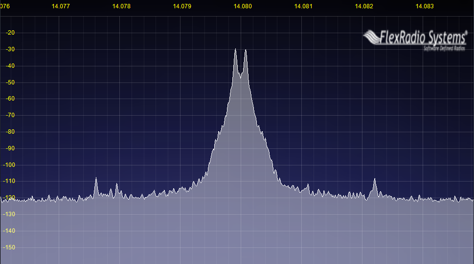
This filter is billed in the manual as a way of filtering out any noise that might be on the audio input. It certainly will do that, but it also has the benefit of filtering the keying sideband energy. The downside is that one cannot use the waterfall tuning with this method, as it would be easy to move your signal outside of this fixed 400 Hz filter. Figure 15 shows the result of MMTTY's unfiltered phase continuous AFSK audio into the K3 with the K3's AFSK filter enabled. The effect of the K3's AFSK filter can be seen by comparing Figure 15 to Figure 4, as both have exactly the same audio input to the K3. Note: I also adjusted the KPA3 bias slightly to improve the radio's transmitted IMD. This seems to have reduced the high-order IMD products to about the level of the phase noise, but the effect on the bandwidth above -70dBc appears negligible at this resolution. Attempts to overdrive the radio resulted in no significant change in the signal bandwidth. Even when transmitting wideband noise into the K3 the AFSK Filter keeps the bandwidth limited. While it is possible to transmit trash that is difficult or impossible to copy if one really tries, the AFSK filter in the K3 makes it unlikely that it would generate much QRM on adjacent channels. I would suspect that other radios that can place a DSP filter ahead of the modulator would behave similarly. This appears to be an excellent safeguard against causing wideband QRM while at the same time reducing the bandwidth of a properly transmitted signal.
Effect of K3 AFSK TX Filter
 |
So far the discussion has compared FSK modulation techniques in the lab. We have seen that it is possible to transmit a much narrower spectrum than simple phase-continuous FSK. To my knowledge (which is far from comprehensive) most radios transmit phase-continuous FSK when configured to use their internal FSK generators, and thus transmit a spectrum similar to that in Figure 4. We also saw that keying sidebands could be drastically reduced outside of about a 400 Hz bandwidth around the signal. At this level the phase-continuous FSK sidebands flare out and decay very gradually between -40 and -70dBc, and are eventually limited by the transmitter's IF filter (assuming it is using one). The real question is this: does this make any practical difference on the air?
Figure 16 shows a snapshot of the spectrum on 20M during the ARRL RTTY Roundup in 2012. This was recorded with a dipole at 20 feet in a noisy suburban neighborhood. Clearly many locations will have lower noise floors and stronger signals than this. This was also taken at a time when 15m and 10m were wide open so the band is not nearly as full as it is at other times. One can see the the noise floor at about the -85dB mark. At this moment there are:
Real contest signals
There are more strong signals like this on the band that do not happen to be transmitting when this picture was captured.
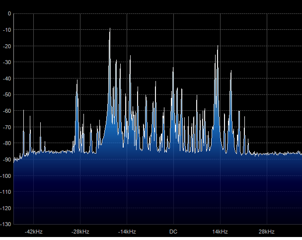 |
If we zoom in on that 75dB signal we can easily see the keying sidebands raising the noise floor by >10 dB out to about 1 KHz either side of the signal. The other spikes you see in the keying sidebands are other stations buried in the keying sidebands--there are in fact two more that are closer to this transmitter, but we can't see (or copy) them at all until the transmitter stops--they are completely buried by the keying sidebands, but are nonetheless more than 10dB above the noise floor.
 |
Note that there is nothing abnormally "dirty" about this signal. These keying sidebands are the result of phase-continuous FSK without any shaping or filtering, and are generated by the vast majority of radios operated in FSK. A survey of just this recording shows that all of the big signals are likely running unshaped phase-continuous FSK (likely using the internal FSK generator in the radio). Most of them are also running amplifiers (we have the contest results). Because their signals are strong the keying sidebands have the ability to cause QRM on adjacent frequencies. You can see the signal flaring out below the -40dBc point. This will sound like key clicks that dissipate as one tunes away from the signal. It is important to note that these sidebands cannot be filtered out at the receiver--the transmitters really are transmitting energy at these frequencies.
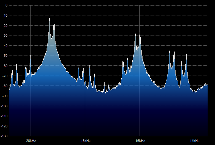
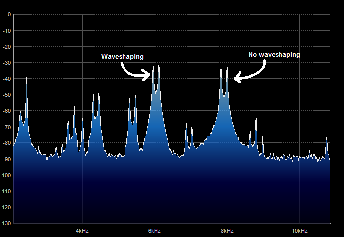
Figure 18 shows two signals of the same strength--about 60dB SNR, or roughly S9 plus a little bit on a quiet band. The signal at 6 kHz has some moderate waveshaping applied resulting in steeper skirts on the transmitted signal (this is most likely MMTTY's default AFSK filter judging by the shape). The signal at 8 kHz is using internally generated FSK, probably with EXTFSK (there is a small amount of timing jitter on the signal which could be explained by the Windows timer). The signals are separated by about 2 kHz. Notice the weaker signal that is approximately halfway between the two large signals. If I tune my receiver to copy this weaker signal I will hear keying clicks from the strong signal above but not from the signal below. The waveshaping allows me to hear the noise floor of the band 500 Hz away, while the unshaped FSK signal does not.
 |
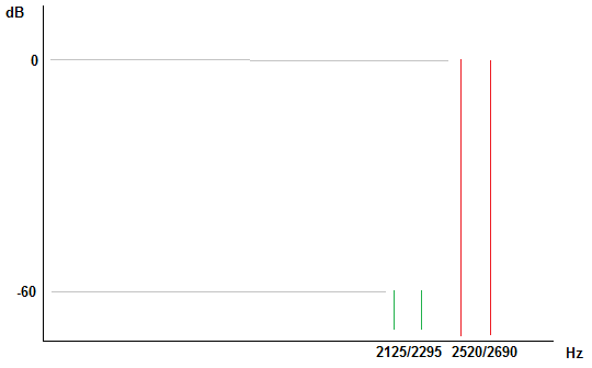
What do these keying clicks sound like? I created a practical demonstration to show what kind of a difference waveshaping can make in terms of contest QRM. I created two signals, one at the usual mark/space tones of 2125/2295 Hz. I then placed an interfering station 395 Hz higher at 2520/2690 Hz with a 60dB stronger signal (see Figure 19). The interfering signal was created with a phase-continuous FSK transmission and also with the 512-tap TX filter in MMTTY.
 |
Here is what they sound like in the receiver:
| Phase-continuous vs. waveshaped QRM |
| Phase-continuous FSK QRM |
| Waveshaped QRM |
Assuming your audio system has the 60+ dB of dynamic range to play this signal, you still might not be able to hear the difference between the two recordings. It turns out that a good software demodulator can easily copy the weaker station in the waveshaped case (in fact, MMTTY can with some profiles).However, most people do not tune around with a wide-open passband in situations like this and instead opt for a narrow roofing filter. I filtered the results through an 8-pole Butterworth filter with a 3dB passband from 2010-2350 Hz and normalized the result. This is like filtering the signal through a 400Hz crystal roofing filter (shifted down slightly) and letting the receiver's AGC equalize the volume to a comfortable listening level. The resulting two sound files are given below. This should sound familiar to anyone who has ever tuned next to a loud station in a contest.
| QRM with roofing filter |
| Phase-continuous FSK QRM filtered by roofing filter |
| Waveshaped QRM filtered by roofing filter |
The waveshaped QRM has reduced its transmitted bandwidth enough for perfect copy of weaker signal only 395 Hz away. There is a small amount of the QRM signal coming through the stopband of the filter, but it is not bad and you can easily distinguish the signal with your ears. The sidebands of the phase-continuous FSK cover the weaker signal far beyond any hope of copy. In fact, this "clean" FSK signal will cover a weaker signal of this strength even if had another 500 Hz of separation!
For those who wish to see it with software, the following files are 60s recordings in the .mmv format that can be replayed in MMTTY. You can see the difference for yourself by using MMTTY's playback option. (Use a right-click to save to disk on Windows systems.) If you have software that will play back a wave file with and 11025Hz sample rate, you can just change the extension from ".mmv" to ".wav".
| Files for MMTTY playback. (Use right-click to save on Windows systems.) |
| Phase-continuous FSK QRM for MMTTY playback |
| Waveshaped QRM for MMTTY playback |
Here are some conclusions that I have drawn from this investigation. The reader should draw his or her own, and I welcome any discussion of the issues they bring up.
It is likely that people just assume that RTTY "key clicks" on loud signals are part of the game because there are so many people generating signals this way. Phase-continuous FSK's sidebands roll of at a rate of 6dB per octave, which is why loud RTTY signals sound disproportionately "wide" in the receiver. It need not be this way. Here are some possible ways to clean things up, in no particular order: