Dual Channel Tube Microphone Preamp
| The Original:. Pultec equalizers
such as the PEQ-1 and
MEQ-5 are the stuff of legend, and command outrageous prices. The
MB-1 is less well known than the equalizers, but prices for original
units are in line with Pultec's reputation for excellent design and
solid construction. The MB-1 contained a single microphone preamp
in a 2U rack mount enclosure 7 3/4 inches deep. The circuit was
designed to supply between 28 dB and 48 dB of gain. The size of the power, input, and output transformers, along with the multisection electrolytic can caps did not make for a compact package. The Triad R-7A power transformer is typical Pultec overkill, rated for 60 mA of 600 VCT output, even though the circuit only requires about 10 mA. The preamp gain, and input and output transformer impedance were settable by the user, but only by installing a fixed resistor and wiring jumper connections inside the chassis. |
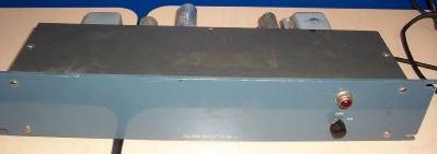 Front panel: a power switch and a pilot lamp 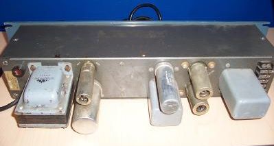 Rear panel: input and output connections are made on a screw terminal barrier strip on the right. Images of original MB-1 shamelessly stolen from gcrep810's ebay auction. |
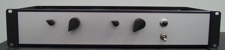
Front panel : each channel has an impedance selector (50, 200, 500 ohms) and a 10 step gain selector (28 dB - 48 dB). Knobs and switches are mil-spec beauties from the surplus store. The 2U rack enclosure is the Sescom 2RU7. It is shipped completely disassembled, and consists of 2 x 0.125" end panels, 4 extruded rails, and 4 x 0.062" skin panels, all anodized aluminum. It is held together by eight screws through the end panels into the ends of the rails. The skin panels slip into slots in the rails. The box becomes acceptably stiff when it's all put together. It's not the most rugged box available, but it'll survive in the studio, or mounted in an SKB (or similar) portable rack box with a DAT machine for location recording.
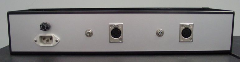
Rear panel: balanced outputs on Switchcraft 1/4" TRS phone jacks, inputs on Neutrik XLR's.
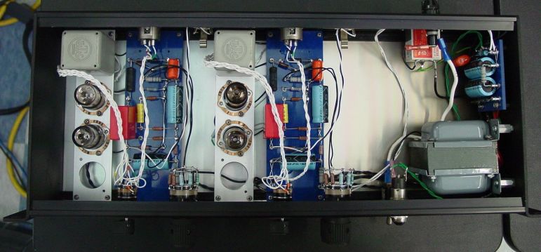
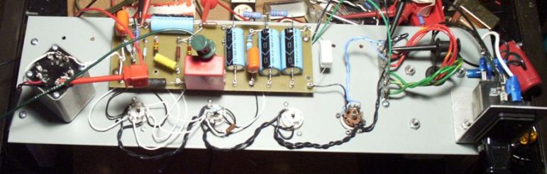
Top view: Two identical preamp modules and power supply fit comfortably in 2U x 7" deep chassis. I probably have enough space left over to add a phantom power supply module, which I intend to prototype in the next few months. The turret boards and tube/transformer mount are attached to threaded aluminum standoffs, that are screwed into a nut captured by the chassis rail extrusions. The Sescom site shows assembly details. The tube and transformer mount is 6.7" x 1.5" x 0.125" Alumi-Trim anodized aluminum cut from a 4' strip bought at the home center. The 1" hole near the bottom allows mounting an octal socket for a plate-to-line output transformer such as the Altec 15095 15K:600 ohm.
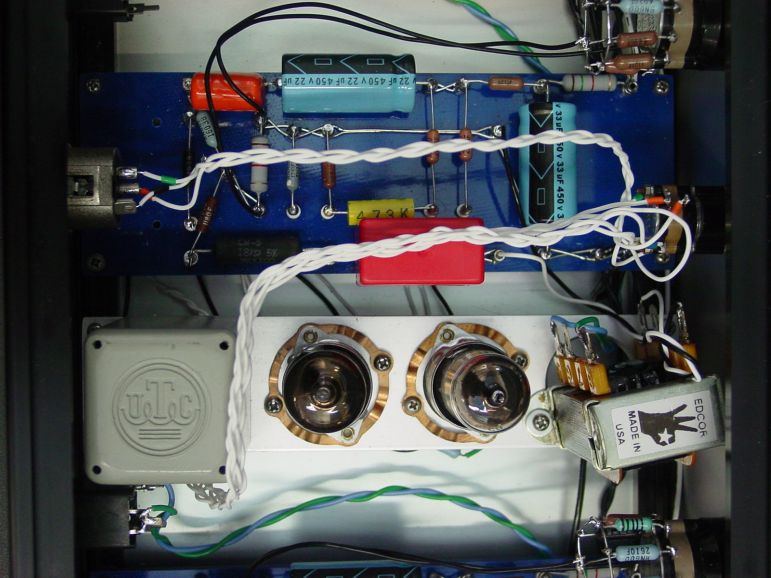
Top view of one preamp channel, after adding output transformers: I originally omitted output transformers, because I did not need balanced output. However, the signal output voltage at the cathode follower's coupling cap was too high (>100V P-P) to feed into any unbalanced line input without major attenuation. NewYorkDave over at GroupDIY turned me onto a line of low cost impedance matching transformers made by Edcor (needs MSIE browser) in Carlsbad, NM. While their standard WSM 10K:600 model would have worked fine, Dave told me they would custom-wind a 15K:600 ohm version for the same price and delivery as the stock item. One week after calling Edcor, 4 freshly varnished 15K:600 plate-to-line transformers arrived by UPS for less than US$10 apiece delivered! Specified response is 20 Hz - 30 kHz +/- 0.5 dB. The WSM's are unshielded, open frame units, but I haven't had any issues with noise pickup, or feedback into other stages of the circuit. The spec'd power level is 500 mW, which is actually higher than the 400 mW spec Triad HS-50's Pultec used in the original. I mounted the transformers sideways over the octal socket hole, attached with a screw through one of the mounting ears which I bent at a right angle. With the transformers, the preamp puts out over 22V P-P into 600 ohms (unbalanced) at clipping.
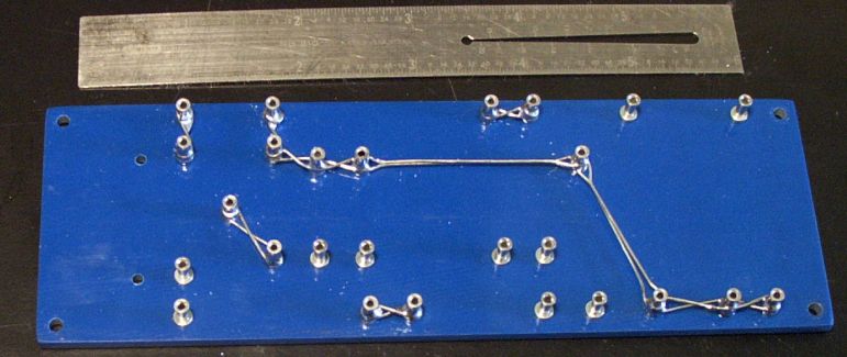
Turret board after buss lacing, before mounting components. It's 6.7" x 2.125" x 0.125" G10-FR4 (Garolite) from McMaster-Carr. I worked out the layout myself, generally following the style I picked up from Doug Hoffman, who supplied the turret terminals.
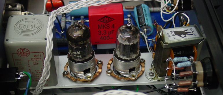
Side view of one preamp channel. On the left is the UTC A-11 mic-to-grid input transformer. The shock-mount tube sockets contain a GE-labeled 12AX7 (Made in Gt Britain), and a Sylvania Gold Brand 5963 (industrial 12AU7). The Wima MKS 4 3.3 uF film capacitor couples the output of the cathode follower to the Edcor output transformer. The cap is hot-glued to a block of Delrin so it doesn't flop around mounted on top of the turret terminals. My 15 year old daughter Karen plaited the 6 strands of #24 teflon over silver plated copper wire that connects the balanced input to the impedance selector and input transformer. All half watt resistors are 1% RN60D metal film. I used a 5W 18K cathode resistor for the cathode follower instead of the 10W specified in the original schematic, because it only needs to dissipate <1.5 W.
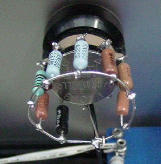
| Gain selector: In the original
Pultec MB-1, the user set the unit to a fixed gain between 28 dB and 48
dB by installing a resistor in the chassis. My DIY version uses a
10-step Grayhill switch on the front panel to change the gain over this
range in 2 dB steps (the first two steps are 3 dB). Gain is
controlled by
varying the amount of negative feedback (NFB) from the cathode follower
to the first gain stage. The neat thing about this is that no
signal is wasted by attenuating voltage dividers anywhere in the
circuit. Furthermore, the NFB further reduces the output
impedance of the cathode follower, so that the preamp's unbalanced
output can drive low impedance inputs directly. The only drawback
is that switching the gain setting puts a large audible transient on
the output. The mixer/recorder level controls can be used
to adjust levels while recording. Rafael Texiera used a 10K
pot in series with a large value capacitor (~200 uF) to get continuous
gain control. I successfully tested his mod, but prefer the step
control's ability to obtain matched and repeatable channel gains. |
 |
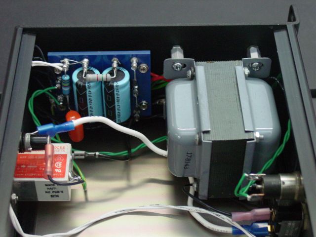
Power transformer is a Triad R-4A, which produces 555 VCT at 40 mA, and 6.3 VCT at 2A with 120 VAC input. The rectifier, first two filter stages, and the filament reference voltage divider on the power supply board are shared by both channels. The 20 mA current needed for two channels still leaves a 100% margin for this transformer, but would drop the voltage a bit lower than the prototype. I used UF4007 silicon diodes instead of the 6X4 tube rectifier of the original and prototype to avoid its 22V voltage drop, along with its plate and filament dissipation. The power transformer and rectifier/filter board are mounted on standoffs threaded into the 1/8" aluminum end panel / rack ear. The transformer is far enough away from the preamp modules so radiated hum isn't an issue.
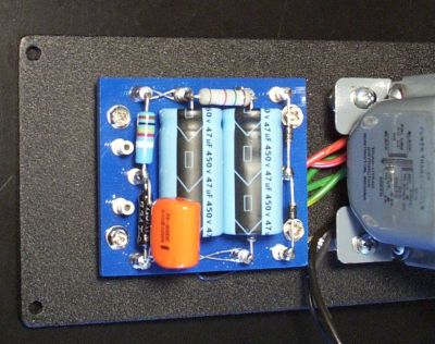
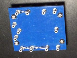 Above: Rectifier/filter turret board laced . Right: mounted on chassis end panel with Triad R-4A transformer. The voltage divider on the left side of the board raises the filament winding center tap 115V above ground. |
 |
Planned enhancements: Switchable pad and phase on the output. Engraved front panel. Switchable 48V regulated phantom power supply.